Introduction to Solid Modeling: Benefits, Applications & Fundamentals in Engineering
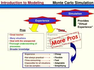
Explore the advantages of 3D modeling, including visualization, engineering analysis, and manufacturing applications. Learn about Finite Element Analysis (FEA) basics, CNC machines, parametric modeling concepts, and design intent in engineering.

Introduction to Solid Modeling: Benefits, Applications & Fundamentals in Engineering
E N D
Presentation Transcript
Introduction to Solid Modeling Parametric (3D) Modeling Introduction to Engineering, E10.
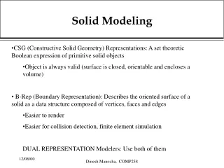
Why draw 3D Models? • 3D models are easier to visualize and interpret. • 3D models can be used to perform engineering analysis, finite element analysis (stress, deflection, thermal…..) and motion analysis • 3D models can be used directly in manufacturing, Computer Numerical Control (CNC). • Less expensive than building a physical model. • 3D models can be altered easily, create more concepts • Can be used for presentations and marketing. Introduction to Engineering, E10.
Old designs - geometric New designs - freeform Introduction to Engineering, E10.
Coffee Press Thermos Radio Mechanical Engineering Dept.
Hull design Freeform shapes Mechanical Engineering Dept.
Basics of Finite Element Analysis (FEA) Why FEA ? Modern mechanical design involves complicated shapes, sometimes made of different materials that as a whole cannot be solved by existing mathematical tools. Engineers need the FEA to evaluate their designs What is FEA ? A complex problem is divided into a smaller and simpler problems that can be solved by using the existing knowledge of mechanics of materials and mathematical tools Introduction to Engineering, E10.
Basics of Finite Element Analysis The process of dividing the model into small pieces is called meshing.The behavior of each element is well-known under all possible support and load scenarios. The finite element method uses elements with different shapes. Elements share common points called nodes. 10-node Quadratic analysis results mesh Introduction to Engineering, E10.
Can Crusher Introduction to Engineering, E10.
A solid model of the part is created. 1 3 The program path is generated by computer 2 Program is entered into MCU via a flash drive or created by onboard computer 5 Programmed instructions sent to CNC machine Part is machined 6 4 Programmed path of cutter is displayed Computer Numerical Control (CNC) A CNC machine is an NC machine with the added feature of an on-board computer. Tool exchanger Machine Control Unit (MCU) CNC machine Introduction to Engineering, E10.
CNC Machines Machining Centers, equipped with automatic tool changers, are capable of changing 90 or more tools. Can perform milling, drilling, tapping, boring… on many faces. Introduction to Engineering, E10.
CNC Face , 3-axis Mechanical Engineering Department
Animation with Exploded View Mechanical Engineering Dept.,
Creating Solid ModelsParametric Modeling Concept • Parametric is a term used to describe a dimension’s ability to change the shape of model geometry if the dimension value is modified. • Feature-basedis a term used to describe the various components of a model. A part can consist of various types of features such as holes, grooves, fillets, and chamfers. • Parametric models are featured-based, solid modeling design programs: • SolidWorks, Creo (PTC), Inventor by Autodesk Unigraphics, Catia, ….. Introduction to Engineering, E10.
Design Intent • In parametric modeling, dimensions control the model. • Design intent is how your model will react when dimension values are changed. Introduction to Engineering, E10.
Design Intent Line not dimensioned The drawing shows the intent of the designer that the inclined plane (chamfer) should have a flat area measuring 2.5 inches and that it should start at a point 1.25 inches from the base of the drawing. These parameters are what the designer deemed significant for this model. 2.50 2.50 1.25 4.00 Remember that the placement of dimensions is very important because they are being used to drive the shape of the geometry. If the 2.5 in. vertical dimension increases, the 2.5 in. flat across the chamfer will be maintained, but its angle will change. Introduction to Engineering, E10.
1.75 In the last drawing, the designer calls for a specific angle for the chamfer. In this case the angle of the chamfer should be dimensioned. 30.0O 2.50 4.00 Design Intent Line not dimensioned 2.125 In this drawing, what is important to the designer is the vertical location and horizontal dimension of the chamfer, rather than the flat of the chamfer. 2.50 1.25 4.00 Line not dimensioned Introduction to Engineering, E10.
Design Intent Introduction to Engineering, E10.
Pattern: 8 Holes • 30 10 60 15 Parametric Modeling The true power of parametric modeling shines through when design changes need to be made. The design modification is made by simply changing a dimension. Since the counterbore is associated with the top surface of the ring, any changes in the thickness of the ring would automatically be reflected on the counterbore depth. Introduction to Engineering, E10.
Sketching and Features When discussing the mind-set needed for working with parametric modelers, two topics need to be expanded: Sketching and Features Sketching • Take the word sketch literally. A sketch should be just that, a sketch. • When sketching it is not necessary to create geometry with accuracy. Lines, arcs, and additional geometry need not be created with exact dimensions in mind. • When the dimensions are added, the sketch will change size and shape. This is the essence of Parametric Modeling. In short, the sketch need only be the approximate size and shape of the part being designed. When dimensions are added, they will drive the size and the shape of the geometry. Introduction to Engineering, E10.
Create a 2D sketch and dimension it 2.75 2.5 1.0 Revolved feature .75 .25 Extruded feature Features Sketching and Features • Create a feature from the sketch by extruding, revolving, sweeping, and lofting. Introduction to Engineering, E10.
Sweep feature Creating Solids - Sweep A Sweep feature requires a profile and a path. The profile will follow the path to create the solid. Profile (section) Path (guide) Introduction to Engineering, E10.
Square profile Round profile • Sections (profiles) do not have to be sketched on parallel planes • All sections must be either closed or open Creating Solids – Loft (different profiles) Round profile Introduction to Engineering, E10.
Creating Features from Sketches Loft in SolidWorks Introduction to Engineering, E10.
Applied Feature • Applied feature does not require a sketch. • It is applied directly to the model. • Fillets and chamfers are very common applied features. Chamfer Fillet Introduction to Engineering, E10.
Applied Features Shell – hollowing out a solid Introduction to Engineering, E10.
Applied Features - Patterns Linear (rectangular) pattern Introduction to Engineering, E10.
Applied Features - Patterns Linear (rectangular) pattern • Select # of features in dir. 1 and 2 • Select direction 1 and 2 • Select feature to pattern • Select spacing in dir. 1 and 2 Introduction to Engineering, E10.
Circular (polar) pattern Applied Features - Patterns • Select # of features • Select axis of rotation • Select feature to pattern • Select spacing between features Introduction to Engineering, E10.