Solid Modeling
Solid Modeling. Ref. Mantyla. Introduction. Aim of modeling: The search of a media of communication. Introduction (cont). Geometric modeling Which parts of the objects are visible to the viewer? Colors?. Solid modeling. Introduction. Taxonomy. Geometric Modeling. Solid Modeling.

Solid Modeling
E N D
Presentation Transcript
Solid Modeling Ref. Mantyla
Introduction Aim of modeling: • The search of a media of communication
Introduction (cont) Geometric modeling • Which parts of the objects are visible to the viewer? Colors?
Solid modeling Introduction
Taxonomy Geometric Modeling Solid Modeling Surface Modeling Voxels CSG B-rep {Alias Designer} Winged Edge Halfedge OpenMesh
Issues of Solid Modeling • (information) Completeness • Integrity • Complexity, Geometric Coverage • What does the object look like? • What is the weight, surface area, of the object • Will the object hit the other object on its path?
Representation Schemes Wireframe Surface Modeling Solid Modeling
A solid representation is a finite collection of symbols (of a finite alphabet) that designate a solid of M. The representation techniques of a given solid modeler define the representation space R of the modeler. Those representations that actually can be constructed by the solid modeler according to its syntax rules are termed admissible. A representation scheme is a relation s:MR. The domain of s is denoted by D and the image of D under s by V. If any valid representation models exactly one solid under s, s is called unambiguous or informationally complete. A representation scheme s is termed unique if all solids have exactly one representation
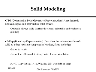
Solid Modeling CSG Constructive solid geometry Volumetric model B-rep Boundary representation
InformationCompleteness • Abletoresolvepointinclusiontestunambiguously • Givenapointandasolid; returnIn/Out/On
Constructive Solid Geometry • Point inclusion test for CSG • Classify against leaf primitives • Propagate the result in the true
Point Inclusion Test for CSG • Classify against leaf primitives • Propagate the result in the tree out IN IN out IN
Volumetric Representation solid otherwise
Boundary Model v f e Face, Edge, Vertex
Validity of Boundary Model non-manifold (next page) Self-intersecting • Elements of the model • should not self-intersect • should not intersect each other unless at their boundary.
Definition of Manifold For every point on the boundary, its neighborhood on the boundary is homeomorphic (topologically equivalent) to an open disc. disc
Plane Models Edge identification Cylinder Torus Mobius strip
Plane Model • Each edge (of a polygon) is assigned an orientation from one endpoint to the other • Every edge is identified with exactly to one other edge • For each collection of identified vertices, the polygons identified at that collection can be arranged in a cycle such that each consecutive pair of polygons in a cycle is identified at an edge adjacent to a vertex from the collection.
Orientable Solids • A plane model is orientable if the directions of its polygons can be chosen so that for each pair of identifed edges, one edge occcus in its positive orientation, and the other one in its negative orientation
Euler-Poincaré Formula (ref) V: the number of vertices E: the number of edges F: the number of faces G: the number of holes that penetrate the solid, usually referred to as genus in topology S: the number of shells. A shell is an internal void of a solid. A shell is bounded by a 2-manifold surface. Note that the solid itself is counted as a shell. Therefore, the value for S is at least 1. L: the number of loops, all outer and inner loops of faces are counted.
Examples Box: V-E+F-(L-F)-2(S-G) = 8-12+6-(6-6)-2(1-0)=0 Open Box: V-E+F-(L-F)-2(S-G) = 8-12+5-(5-5)-2(0-0)=1 Box w/ through hole: V-E+F-(L-F)-2(S-G) = 16-24+10-(12-10)-2(1-1)=0 Box w/ blind hole: V-E+F-(L-F)-2(S-G) = 16-24+11-(12-11)-2(1-0)=0 V-E+F-(L-F)-2(S-G) = 10-15+7-(7-7)-2(1-0)=0 Invalid solid yet stillyields ZERO!
Count Genus Correctly G = ? G = 3? G = 2!
Euler Operators MVFS KEMR MEV MEF (Ring: loop)
Winged-Edge Data Structure • Commonly used to describe polygon models • Quick traversal between faces, edges, vertices • Linked structure of the network • Assume there is no holes in each face
Winged-Edge Data Structure • vertices of this edge • its left and right faces • the predecessor and successor when traversing its left face • the predecessor and successor when traversing its right face.
Winged-Edge Data Structure Edge Table
Winged-Edge Data Structure • the vertex table and the face table
Winged-Edge Data Structure • For a face with inner loops are ordered clockwise. • Adding an auxiliary edge between each inner loop and the outer loop
Halfedge Data Structure • Modification of winged edge • Since every edge is used twice, devise “halfedge” for this use • Can have loop to account for multiply connected face (face with multiple boundaries) • Can handle • Manifold models • Face with boundary • OpenMesh: a specialized halfedge implementation (for triangular meshes)
Half-Edge Data Structure • Doubly connected edge list
Object File Format(OFF) • Storing a description a 2D or 3D object • Simple extension can handle 4D objects • 4D: (x,y,z,w) • OFF File Characteristics • ASCII (there is also a binary version) • Color optional • 3D • No compression
Polygon File Format • Stanford Triangle Format • Store 3-d data from 3D scanners • Properties can be stored including • color and transparency • surface normals • texture coordinates • data confidence values
Stanford 3D Scanning Repository (url) Cyberware 3D Scanners (url) Large models also avaiable at GeogiaTech
Polygon File Format • PLY structure • Header • Vertex List • Face List • (lists of other elements)