Download
1 / 30
310 likes | 410 Vues
Learn about wireframe and solid modeling processes in 3D CAD with Open Inventor 2015 Pro. Discover additive and subtractive techniques to create virtual 3D objects efficiently.

E N D
Additive and Subtractive Solid Modeling Open Inventor 2015 Pro Get out your notebook for jotting helpful ideas from the presentation and while you create your models.
Learning Objectives • Understand additive and subtractive modeling. • Be able do create a 3D model in Inventor from a sketch.
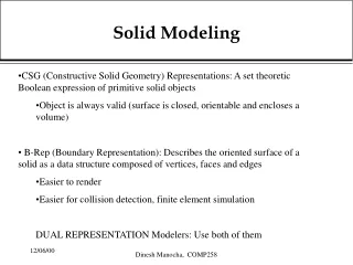
Wireframe Model Solid Model Solid Modeling • Solid modeling is a type of 3D CAD process that represents the volume of an object, not just its lines and surfaces
Wireframe Model Solid Modeling A wireframe model does not give the viewer an idea of surface appearance, nor does it provide information regarding mass properties. Wireframes are not solid models.
Solid Model Solid Modeling A solid model will show how an object’s surfaces will appear, and provides information on surface area, volume, and weight.
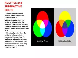
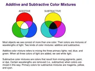
Solid Modeling Solid CAD models are the result of additive and/or subtractive processes. • All CAD solid modeling programs utilize additive and subtractive modeling methods to create virtual 3D objects. • They are also referred to as Boolean operations, named after the 18th century English mathematician Charles Boole.
Additive Methods • A three dimensional object can be viewed as the combination of two or more simple forms. • In the creation of real world objects, this method is represented by construction processes such as welding, gluing, mechanical fastening, and joinery.
Additive Methods 0.75 in. 0.75 in. 0.75 in. 0.75 in. Method 2 Method 1 Method 3
Moving to Inventor 1) Click here to Start. 3) Standard ipt. For starting a Part file. 2) Click on New 5) Select Create 4) Select Project
Start with a Sketch 1) Select ‘Create 2D Sketch’ from the Applications Menu
Pick a Plane Click on a Plane to select it.
A Little Sketchy 1) Select Line. 4) Note how the icon changes. Make this 0 deg. 3) You can enter the length of this side. (2.25) 2) Select starting point for the line..
Fixing Mistake If you have not set constraints, you can double click on a measurement and correct it.
Finish the Sketch Finish Sketch
Your Turn – Additive Methods STEP 1 – Create a portion of the part with a constant thickness • Sketch and dimension a shape to represent a portion of the part with a constant thickness. • Extrude the shape to the appropriate thickness.
Extrude 1) Select Extrude 2) Select the side you will extrude 3) Select the distance (0.75) you will extrude the piece.
Your Turn – Additive Methods STEP 2 – Add a portion of the part with a constant thickness • Apply a sketch plane to an appropriate flat surface • Sketch and dimension a shape to represent another simple form (constant thickness) • Extrude the shape to the appropriate thickness
Select Side as Sketch Plane 2) Create a 2D Sketch. 1) Select the side to add material.
Create Sketch for the Next Extrusion 1) Try using the Rectangle 3) Click on Finish Sketch when complete 2) Enter the lengths for the sides. (0.75) Hit the Tab key to jump from the measure of one side to the measure of the other side.
Your Turn – Additive Methods Final Part
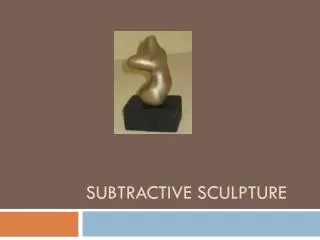
Subtractive Methods • An object can be viewed as the remainder of a solid block that has had the geometry of one or more forms sequentially removed. • In the creation of real world objects, this method is represented by milling, drilling, turning, grinding, and other manufacturing processes.
Subtractive Method in Inventor • This is done by Extruding a Sketch into a part. Extruding into a part.
Your Turn - Subtractive Methods STEP 1 – Create a rectangular solid to enclose the object • Sketch a 2.25 in. x 1.5 in. rectangle • Extrude the rectangle 1.5 inches
Your Turn - Subtractive Methods STEP 2 – Remove material from front face 0.75 in. • Create a sketch on the front face. • Sketch the shape to be removed. • Extrude Cut the shape.
Your Turn - Subtractive Methods STEP 3 – Remove unnecessary material (upper right corner) • Create a 2D sketch on the newly created face. • Sketch the shape to be removed. • Extrude Cut the shape.
Your Turn - Subtractive Methods Final Part
Combining the Methods • Most objects can be modeled efficiently through the combination of both additive and subtractive methods. • There is no right or wrong way to generate a solid model. However, the process that uses the least number of steps in the shortest amount of time is the most efficient way.
Additive Subtractive 1. 2. 3. 4. Result Subtractive Your Turn - Combining the Methods Activity: Complete the models described in ‘4.1g ModelCreation’ document from the assignments folder. When completed with each model turn it in as YourName4.1g1, YourName4.1g2, …
Hints and Shortcuts • Scroll to Zoom • Hold the Scroll down and move mouse to move • ‘Esc’ key to back out of an action • Ctrl-Z to undo an action • To delete. Click on the line and hit ‘Delete’ • To create a sketch on a side: Right click on side and ‘New Sketch’ • Changing Units • Tools -> Options -> Document Settings -> Units Tab • You can add temporary lines to locate corners and delete the temporary lines later. • Dimension: New Sketch, Line, Click on Dimension, select two lines that represent the length, drag dimension line