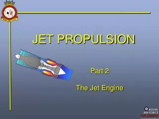
JET PROPULSION
JET PROPULSION. Part 2 The Jet Engine. Combustion. The Gas Path and Temperatures. The shaded area is called the ‘ GAS PATH ’. As air passes through the engine its temperature changes, first by compression, then by adding and burning fuel. The amount of thrust is determined

JET PROPULSION
E N D
Presentation Transcript
JET PROPULSION Part 2 The Jet Engine
Combustion The Gas Path and Temperatures The shaded area is called the ‘GAS PATH’. As air passes through the engine its temperature changes, first by compression, then by adding and burning fuel. The amount of thrust is determined by the change in velocity of the mass airflow. Compression
Combustion Above ambient Ambient temp 450 Deg C 2,500 Deg C 1,000 Deg C The Gas Path and Temperatures Temperature changes cause the shaft and casings to expand and contract. But by different amounts ! These sections expand first and put tremendous unwanted forces on the casings, shaft and rotor.
Combustion Front Bearing Chamber Centre Bearing Chamber Rear Bearing Chamber Roller Bearing Roller Bearing Ball Bearing The Gas Path and Temperatures The solution is in the bearings The bearings are selected to allow expansion (and contraction on cool down) without causing undue stresses. We will examine this more in Part 6
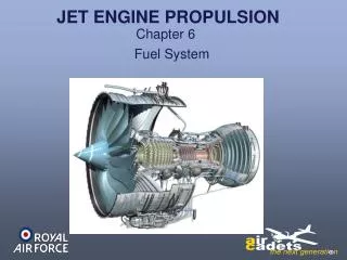
Combustor Operation THE COMBUSTION PROCESS We’re going to look at what happens here The Combustion Chambers Because its the COMBUSTORS that produce the energy for thrust. But first we’ll look at the layout of the combustion system.
OUTER CASING Combustor Operation Combustion Chambers (Cans) Engine Structure and Shaft We will convert this to a basic diagram form
INNER CASING OUTER CASING Combustor Operation 1st JET ENGINES Each CAN has a Fuel Spray Nozzle (FSN) WHITTLE etc. Flame is contained within these tubes ‘FLAME-TUBE’ Engine Structure and Shaft Individual Can Type Combustion Chambers
Combustor Operation The next design had all the cans connected together to equalise pressure and to spread the flame during start-up TYPICAL OF DART SERIES TURBO PROPS IGNITERS Connected Can Type Combustion Chambers
Combustor Operation A disadvantage of Individual Can and Can-Annular combustion chambers is, fluctuations can occur in the turbine blade temperature. To overcome this THE ANNULAR LAYOUT was developed
Combustor Operation TYPICAL OF MODERN BYPASS ENGINES This design features both an annular outer casing as well as an inner annular flame tube and is the design of choice for modern engines. Annular outer casing THE ANNULAR LAYOUT Annular inner casings & flame tube
The Combustion Process Single Can Layout Can Annular Layout THE CROSS SECTION OF ALL THESE LAYOUTS IS VIRTUALLY IDENTICAL AND THEREFORE SO IS THE AIRFLOW Annular Layout
The Combustion Process Outer Combustion Casing Inner Flame Tube 82% Cooling Flow 18% Vortex Flow Recirculating Vortex F S N Approximately 82% of the air from the compressor passes around the inner flame tube and then into it via a number of ‘dilution’ holes. • The other 18%of the air passes into the flame tube :- • half swirls into the flame tube, the rest passes around • swirl vanes to produce a ‘Re-Circulating Vortex’.
The Combustion Process Outer Combustion Casing Inner Flame Tube 82% Cooling Flow 18% Vortex Flow Recirculating Vortex Ignition F S N The fuel is sprayed in under high pressure. The Recirculating Vortex ensures good air and fuel mixing at a ratio of 15:1 (by weight) and therefore efficient combustion.
Check of Understanding What type of combustion chambers did the Whittle type jet engines have? Individual Can Type Annular Type Can Annular Type Continual Type
Check of Understanding How is the thrust of a jet engine determined? • By the change in velocity • of the mass airflow • By the mass air flow • and jet pipe pressure By the mass air flow and velocity By the air temperature and velocity of the mass airflow
Check of Understanding Approximately how much of the mass airflow through the combustion section is used for the dilution (flame cooling) airflow? 9% 18% 62% 82%
Check of Understanding Which part of a jet engine produces the energy for thrust? The Turbine The Compressors The Exhaust The Combustors
Check of Understanding What is a disadvantage that individual can and can-annular type combustion chambers have? They are very difficult to start, accelerate, decelerate and stop The turbine gas flow can be slower Turbine blade temperature fluctuations can occur Turbine speed can be lower
Check of Understanding Approximately how much of the mass airflow through the combustion section is actually used for combustion? 9% 18% 54% 64%
Check of Understanding What is the nominal air to fuel ratio supplied to an engine? 15:1 10:1 5:1 1:1
JET PROPULSION End of Presentation