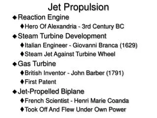
Jet Propulsion and Compressor Design
360 likes | 596 Vues
Jet Propulsion and Compressor Design. NASA's X-43A. Keith Larson. IC Engines and Propulsions Systems. Spring 2005. Professor. Dr. Chiang Shih. Fluid Machinery. Positive Displacement Working fluid is confined within a boundary.

Jet Propulsion and Compressor Design
E N D
Presentation Transcript
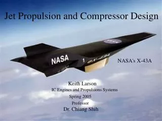
Jet Propulsion and Compressor Design NASA's X-43A Keith Larson IC Engines and Propulsions Systems Spring 2005 Professor Dr. Chiang Shih
Fluid Machinery • Positive Displacement • Working fluid is confined within a boundary. • Energy transfer is by volume changes due to the movement of the boundary. • Dynamic • Working fluid is not confine within a boundary. • Energy transfer is by dynamic effects of the rotor on the fluid stream.
Dynamic Machine A.K.A. Turbomachines • Radial-Flow - Also called Centrifugal. - Radial flow path. - Large change in radius from inlet to outlet. • Axial-Flow - Flow path nearly parallel to the axis of rotation. - Radius of the flow path does not very significantly. • Mixed-Flow - Flow path radius changes only moderately.
Turbomachines that extract energy from the fluid stream Turbines Turbines use Vanes, Blades, or Buckets attached to the turbine shaft. This assembly is called the Rotor, Wheel, or Runner. Bourn, Cambridgeshire, England Colvin Run Mill near Dranesville, Virginia
Turbine Classifications • Hydraulic Turbines - The working fluid is WATER. - Flow is incompressible. • Gas and Steam Turbines - Density of the working fluid may change significantly. Further Classification • Impulse Turbines - Driven by one or more high-speed free jets. - Each jet is accelerated in an external nozzle. - Fluid acceleration and pressure drop is external to the blades. • Reaction Turbines - Part of the pressure change takes place externally and part takes place within the moving blades.
The turbine extracts energy from the fluid stream and converts it into mechanical energy, which is then transmitted through a shaft to some load. The Steam Turbine Generator Satsop Development Park
Or the load could be a compressor within a Turbocharger for an automobile, or a compressor in a jet engine.
Turbomachines that add energy to the fluid stream • Pump - when the fluid is a liquid or a slurry. • Very small to very large pressure rise. • Rotating element is called an impeller. • Fans, Blowers, or Compressors when handling a gas or a vapor. • Fans - generally have a small pressure rise (< 1 inch water) • Blowers - moderate pressure rise (1 inch of mercury) • Compressors - very high pressure rise (up to 150,000 psi)
Pa Po Ai T=Ai(po-pa) T Pa T ue Pa T Po ua Jet Propulsion Principle (Thrust) Pa Po T: Thrust Pa: Ambient Pressure Po: Internal Pressure ue: Exit Velocity Po Steady-Flow . T=mua ua: Mass-average Exhaust Velocity
Thrust per Unit Energy Consumption (Rocket vs. Propeller) . u ue T=ma(ue-u) Engine . . . . T T E E Acceleration of a stream of air through a Propeller Propeller Thrust Ratio Assume a best thermal efficiency of 40%, the maximum possible value of propeller thrust ratio becomes.
Rocket • Tmpuer • • E Rocket Thrust Ratio T • E Estimate ratio of propeller and rocket thrusts Assume that the rocket exhaust velocity is 5000m/s. T T T T
Summary of Propeller and Rocket Thrust • For Aircraft propulsion the big advantage of using a propeller is that less fuel must be carried on board. • The rate of airflow through the propeller can be as much as three orders of magnitude larger than the rate of fuel consumption of the driving engine. • Propulsion using a propeller has much better efficiency when compared to propulsion with a rocket. • The aircraft using a propeller can travel much greater distances before having to refuel.
Air Motion Axis of Rotation w1t u Ut Blade Motion u w2t D ue u c2 w1t Propeller Theory Air Velocity (u) Blade Speed (Ut) Relative Approach Velocity (w1t) Relative Leaving Velocity (w2t) Swirling Velocity (u) Axial Component of Leaving Velocity (ue) Leaving Velocity (c2) Turning Angle () Ut
Limitation of the Propeller in Propulsion In order to maintain good flow over the blade certain conditions must be meet. 1. The relative approach angle and the blade leading edge angle must be close to prevent flow separation from the blade. 2. The turning angle must be keep quite small, or the flow will also separate from the blade. 3. The relative approach velocity must not be too close to the speed of sound. This is to prevent shock waves from forming on the blade. Thus conventional propellers are used for flight speeds well below the speed of sound; usually at or below 135 m/s (300 mph).
Blade speed too high Flight speed too slow Operating outside of design parameters w1t u Ut Air Motion Air Motion Axis Axis Blade Motion Blade Motion w1t Poor design: Turning angle is too large u Ut
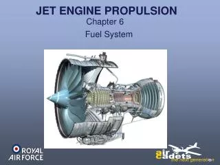
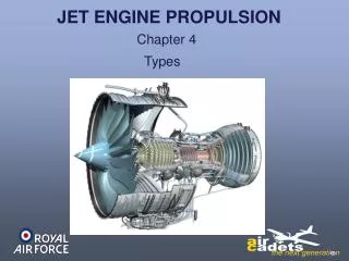
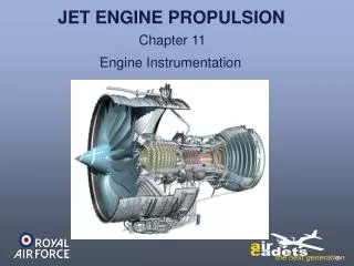
The Importance of the Compressor/Turbine in Modern Flight It was not until 1939 that a compressor, combuster, and turbine were coupled together to create the first turbo engine for aircraft propulsion. Exhaust Gas Out Air Inlet
1. The turbine engine made supersonic flight possible in aircraft 2. Reduced the cost of air travel. 3. Lead to great improvements in aircraft safety.
Turboprop Allison T56 Turboshaft
Turbofan General Electric CF6 Turbofan
Turbojet General Electric J79 Turbojet with Afterburner
Turbo Engine Comparison • Turboprop • Medium-speed • Moderate-size craft • High efficiency • Limited flight speed • Geared transmission • Turbofan • Internal Propeller • Supersonic speeds • High bypass airflow • Med/High efficiency • No gearbox • Turbojet • High speed • Mach 4 • Low airflow rate • Low efficiency • High op temps NOTE: Due to the ram compression due to flight speed, the optimum compressor pressure ratio (CPR) goes to zero around Mach 4. CPR 30:1 for subsonic flight. CPR 10:1 @ Mach 2. Compressor not needed at Mach 4; Ramjet.
Comparison of the Axial-Flow and Radial-Flow Compressors Axial-Flow compressors do not significantly change the direction of the flow stream, thus Axial-Flow Compressor allows for multiple stages. Radial-Flow Compressors can not be staged. While the Radial-Flow Compressor has a larger Compressor Pressure Ratio (CPR) per stage, the multi-stages of the Axial-Flow compressor allows for a larger overall CPR. The frontal area for a given air flow rate is smaller for an Axial-Flow Compressor than for a Radial-Flow Compressor. The Axial-Flow Compressor has a higher efficiency. Disadvantages are the higher cost to manufacture the Axial-Flow Compressor, and the Radial-flow Compressor is more durable than the Axial-Flow Compressor.
Example Problem Given a first single stage of an Axial Compressor with the following conditions: ambient pressure (Pin) 1 atmosphere, ambient temperature (Tin) 300K, aircraft cruising speed (Vin) 170m/s, median blade diameter (D) 0.5m, rotor rpm (Urotor) 8000rpm, turning angle () 15 degrees, specific heat ratio () 1.4, air mass flow rate (mdot) 35kg/s, and (Cp) conversion factor 1004 m2/s2*K, calculate the first stage Compressor Pressure Ratio (CPR).
W1 Vin U Step 1. Create the velocity triangle and calculate the relative speed of the rotor blade from the rotational velocity. Blade motion
W1 Vin U Step 2. Calculate the air to blade relative velocity and the angle between the relative and actual air speed.
W2 Vin Step 3. Axial velocity (Vin) does not change. Calculate relative exit angle(2), then portion of the relative blade speed (Uw2). Calculate relative air speed (W2)
Step 4. Calculate the portion of the relative blade speed associated with the actual air velocity (Uv2), the calculate the actual air speed (V2). V2 W2 Vin
The Compressor Pressure Ratio (CPR) is found from the isentropic relationship. To1 is calculated from the following equation. To2 has to be calculated from the specific work of the compressor stage.
Specific work of the stage is calculated from the torque of the shaft, angular velocity of the blade, and mass flow rate of the air. Torque of the shaft is: No initial tangential component to the inlet velocity. Power of the shaft is:
Specific work of the stage is then: Now To2 can be calculated from the specific work To1, and the conversion factor.
Finally, the Compressor Pressure Ratio can be calculated!!! The answer is:
The engines on the blackbird are turbojets and are used as such up to about Mach 4; when the air flow is bypassed around the compressor and the engines become ramjets. Lockhead SR-71 Blackbird
NASA X-43A This is where we are today. The X-43A is an experimental aircraft that uses a scramjet (supersonic ramjet) for its propulsion. The X-43A has reach speeds of about Mach 10.