MAGNET MAPPING
This project involves mapping the magnetic axes of four superconducting magnet modules to align them with the beam axis. The goal is to achieve alignment within 0.5 mm tolerance. The mapping procedure includes surveying and analyzing the magnetic fields using hall probes and applying corrections to ensure accurate measurements. The results show the positions of the magnetic axes and highlight discrepancies that need to be addressed. The study also examines the alignment of the tracker and its implications for data analysis. Future work involves refining installation procedures and repositioning modules to improve alignment.

MAGNET MAPPING
E N D
Presentation Transcript
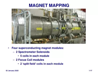
MAGNET MAPPING • Four superconducting magnet modules: • 2 Spectrometer Solenoids • 5 coils in each module • 2 Focus Coil modules • 2 ‘split field’ coils in each module FC SSD SSU
INTERNALLY • Currents ~ 200 Amps; Fields up to 4 Tesla axially • Rigid cold – warm supports support forces up to 25 tons • Dimensions of coils known to ~ 0.1 mm • Physics says align axes to 0.5 mm wrt to beam axis... Tracker Focus Coil 2 coils on one bobbin Spectrometer Solenoid 5 coils on one bobbin
TOLERANCES • MC study of trajectory of initially on-axis muons for sets of coils with • Randomly offset axes • Randomly tilted axes • within fixed radius circle at each end of each bobbin • Tilts more important than offsets • Study was for STEP VI Align bobbin axes to 0.5 mm wrt beam axis • Step IV less critical; DMIC not studied Offsets Tilts
MAPPING GOALS • Find magnetic axes of the magnets • with respect to fiducials • Align modules so that magnetic axes on beam axis • Ideally to better than 0.5 mm • Check alignment in Hall • Check fields agree with calculated fields • and / or • Find effective conductor dimensions
THE CERN MAPPER Seven 3-axis Hall probes r = 0, 30 … 180 mm Disc moves longitudinally Disc can be rotated
PROCEDURE • Mapping: • Mapper placed (approximately) on module axis • Survey wrt module fiducials • Longitudinal (z) scan at fixed angle of disc (f ) • Change f and repeat • Repeat at different currents • Analysis: • Transform field components to Cartesians in Mapper system • Apply survey corrections • Apply Maxwell: • Corrections (probe rotations) to ensure curl B = 0 • Use div B = 0 to obtain axis • Transform axis to module fiducial system • Sounds easy... but
Huge amount of data • Subtly different between modules • Several surveys • Subtly different between modules • Several transformations • Easy to get wrong • Mechanics of mapper • Enough material for several D. Phil theses...
CURL CORRECTION Field vectors in plane of mapper disc • Probes measure Bz , ‘ Br ’ and ‘ Bf ’ in system of mapper disc • Small rotations of probes apparent curl • Determine rotations & correct Before After
AXIS FINDING • Magnetic axis Bperp = 0 • Maxwell-Gauss: • Expect Bx to be linear in x close to axis: Bx = k(x –x0) + aBzat each z x0 is axis ais angle between mapper and magnetic axes • Fit to find axis: x0 = p + a z • Model independent
SURVEY CORRECTIONS dY versus X FC2 SSD • Mapper disc doesn’t move in straight line • Transverse movement surveyed for each module • < 0.6 mm for FCs • ~ 2 – 3 mm for SSU & SSD • Survey corrections applied to x and y coordinates
SOME FIELDS FC2 SSD • Same scale for Bx and Bz • 8 (x,y) points at each z • Information about axis from where Bz changing fastest
FIT RESIDUALS & ERRORS Horizontal FC1 Flip Mode Vertical • Fit residuals ~ a few Gauss • Clear systematic effects • Attributable to mechanics of mapper • Comparison of different runs • Axis positions known to 0.1 – 0.3 mm • Good enough
RESULTS • Magnetic axes of modules • Determined to < 0.3 mm • Found to be within ~1mm centres of module flanges • except for SSD • 4 mm discrepancy at one end • 11 mm at other end • Checked with simple vector plots – unambiguous • Manufacturing error (SSD has a chequered history...) • Can it be accommodated? SSD upstream SSD downstream
IN PRACTICE • Modules coupled by bellows • Little transverse compliance • Some manufacturing errors • Determine installed positions of modules • SSD magnetic axis 8 – 9 mm off beam axis • Do the data concur?
TRACKER – FIELD ALIGNMENT • Data taken with each SS independently • Fit to obtain angle of Tracker axis – SS magnetic axis • Field lines are axis of helical trajectory • Results not inconsistent with known (mis)alignments • But complicated by slowing of muons in tracker planes • Work in progress
CONSEQUENCES • MC studies of real misalignment • Not a big effect for Step IV measurements • but not desirable (obviously) • Data taken to • Confirm/check alignment of Trackers in SSU & SSD • Not inconsistent • Alignment of FC • Analyses ongoing • Use current hiatus to fix problem: • Metrology of module flanges • Manufacture new bellows to allow for offset axes • Refine installation procedures • Re-position modules