Simulating Material Property Changes of Irradiated Nuclear Graphite
310 likes | 547 Vues
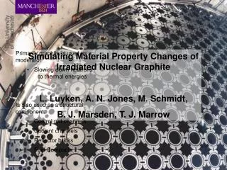
Primarily graphite is used as a moderator Slowing down neutrons to thermal energies Is also used as a structural component. Control rod channels Coolant channels Reflector bricks Fuel Compacts. Simulating Material Property Changes of Irradiated Nuclear Graphite

Simulating Material Property Changes of Irradiated Nuclear Graphite
E N D
Presentation Transcript
Primarily graphite is used as a moderator • Slowing down neutrons to thermal energies • Is also used as a structural component. • Control rod channels • Coolant channels • Reflector bricks • Fuel Compacts Simulating Material Property Changes of Irradiated Nuclear Graphite L. Luyken, A. N. Jones, M. Schmidt, B. J. Marsden, T. J. Marrow
What Happens to Graphite in a Reactor Core Components Deform Material Properties Change Simple Dose Profile
Graphite Microstructure Nuclear Graphite is made up of; Filler Particles -Ordered Crystallites Binder Matrix - Disordered Crystallites Porosity - Calcination cracks - Gas evolution pores Pechinay Bulk Structure (polarised optical image)
Graphite Microstructure Crystallite Structure. Crystal Mrozowski cracks Crystallite Structure (Image Abbie Jones)
Damage Mechanism Graphite Structure Standard Model Ruck, Tuck and Buckle
Damage Mechanism a C a Crystallite Structure (Image Abbie Jones)
Simulating Irradiation Damage • Initial Adsorption “unpins” layers • Intercalate can then penetrate graphite planes. • Intercalate concentration within microstructure dependant on partial pressure of surrounding atmosphere. • Bromine can also fill dislocation ribbons and push planes further apart Widening of Dislocation Ribbons on Intercalation
Dimensional Change by Intercalation (Presented at UNTF 2009) Strain due to Bromination of polycrystalline graphites Strain due to Bromination of HOPG • Single crystals experience high strain at low bromine concentration • Polycrystalline graphites experience differing bulk strains depending on orientation of crystals
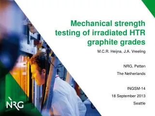
Tomography at the Swiss Light Source Experimental Set Up X-Ray Source Shutter Bromine Rig Camera Beam Energy: 28KeV (high) Projections: 1501 (reduces noise) CCD exposure time: 160ms (fast) Binning: 2 x 2 (reduces image resolution)
Filler Binder Brominating Graphite Microstructure
Filler Bromine quickly permeates large crystalline regions Filler Nevertheless the largest deformation vectors are seen in the filler particles Binder However larger regions of the binder matrix accommodate bromine due to greater open porosity in this region Brominating Graphite Microstructure
Change in Young’s modulus Where E = Young’s modulus ρ = density ν = sonic velocity θ = Poisson's ratio Experimental Setup
Change in Young’s modulus ** literature values vary from 4GPa to 7GPa
Conclusions • Bromination produces bulk dimensional • Initially penetrates binder phase due to large amounts of open porosity • Later quickly fills filler phase • Largest strains are seen in filler phase • As with irradiation brominating graphite increases the young’s modulus.
Future Work • Investigate crystal strains due to bromination. • Applied for beam time at ILL • Further develop Young’s modulus experiment to measure bulk strain insitu • Use laser displacement detector
Thank you James Perrin University of Manchester David James University of Manchester Paul Townsend University of Manchester Sam Macdonald University of Manchester (Swiss Light Source) Will Bodel University of Manchester "This work was carried out as part of the TSEC programme KNOO and as such we are grateful to the EPSRC for funding under grant EP/C549465/1“ Questions?