Download
1 / 19
220 likes | 540 Vues
Southern California Edison’s AMI Systems Design. “Technology Advisory Board”. System Design Goals. Develop requirements that anticipate customer needs and support policy objectives through 2012

E N D
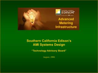
Southern California Edison’sAMI Systems Design “Technology Advisory Board”
System Design Goals • Develop requirements that anticipate customer needs and support policy objectives through 2012 • Develop an architecture framework leveraging leading industry methodologies and principles that support SCE’s AMI solution as a strategic platform to enhance customer service and grid reliability • Use a systems engineering approach to conduct trade-off analysis focused on the value of enabling scenarios in the AMI business case • Select designs and technologies that mitigate the risk of rapid technology and functional obsolescence
Future-proofing SCE’s AMI Solution • Given the varied pace of technology advancement in the meter and communications industry the risk of technology obsolesce to AMI is high • In order to manage this risk the AMI program focused on the following: • Understanding the market and vendor solutions & technologies • Developing the layered architecture necessary to meet our requirements, assess vendor offerings and understand any gaps • Developing strategies and technical points of view with an emphasis on future-proofing SCE’s AMI solution against the risk of rapid technical obsolesce • Communicate with the industry to help increase the pace of innovation and ensure basic architecture elements necessary for future-proofing are available for SCE’s implementation
Understanding Electric Residential Meter Technologies 2nd Generation vs. 3rd Generation difference in adoption of architecture based design SCE Technology Adoption Zone Smart Meters Gen3 $65 Performance (Functional & Value) $110 Solid State Gen2 2000 2006 2008 2010 Time
Understanding Electric Meter Communication Technologies Technology choices based on solving majority solution with an effective engineering economic alternative while recognizing the rapid rate of communications alternatives SCE Technology Adoption Zone Pervasive Customer Broadband Access AMI BPL v3 Muni WiFi WiMax Performance (Bandwidth, Coverage & Value) RF Mesh PLC v2 BPL v2 Broadband Application for Advanced Metering RF Canopy BPL v1 AMR ERT 2000 2006 2008 2010 Time
Developing SCE’s AMI architecture • SCE’s Systems Engineering approach provides a method for decomposing complex systems into manageable elements using “Systems Thinking” approach • AMI is a System of Systems • A collection of independent systems organized to perform collaboratively to achieve a purpose not achievable by the individual systems • Systems Levels are iteratively described in increasing levels of detail as the AMI architecture progresses to lower levels of abstraction
AMI requirements-driven architecture perspectives Development of conceptual, component & reference architectures has allowed us to examine AMI from a number of architecture perspectives (Operational, System, Technical) • Use Cases & Business Scenarios • Requirements • Information Needs • Technical capabilities required to support uses of AMI • Component Architectures • Message Architecture • Reference Architecture • Open standards available to support architecture • Vendor solutions and offerings • Enabling enterprise standards, patterns & services
Conceptual Architecture Development Approach This process was used to: • Develop requirements • Functional • Non-functional • Understand Vendor Capabilities • Develop a platform-independent component architecture • Understand candidate standards • Understand the message architecture necessary to support the requirements • Map requirements to enabling components • Understand gaps between vendor offerings & architecture needed to support the requirements Conceptual Architecture
AMI Conceptual Component Diagram Edge Data Center • Data Center Aggregator • System Management Console • Meter Data Management System Field Elements • Repeater • Distribution Automation Nodes • Neighborhood Aggregators Customer Premise • Premise Gateway • AMI Meter • Other Meters • Load Control Devices • In-home display • Building Management System • Programmable Communicating Thermostat (PCT)
Electric Meter Communication Strategy • Technology choices need to balance standards, performance and cycle time • Reach for greater relative bandwidth (still in narrow range) for 2-way comms • Mitigate exposure to fast cycle technologies touching large number of elements • Reliability and Security are significant issues • Commercial risk mitigation • Layered the network architecture to take advantage of the constantly evolving communications landscape
AMI Meter & Device Strategies 1st Level: High level component This layer provides a common framework to understand scoping boundaries and vendor offerings 2nd Level: Programmable elements This layer includes a programmable layer that provides capacity for remote deployment of additional capabilities to adapt to changing customer needs and market conditions 3rd Level: “Logical” device layer This layer is Including an event bus architecture and shared resources which provides additional flexibility and extensibility for the future
AMI overall systems strategies • Use the AMI Home Area Network (HAN) controller in the meter to stimulate a robust eco-system of energy management products that provide customers with new tools to manage their electricity usage and allow SCE to develop new programs • Fast cycle technologies run the highest risk of obsolesce so we shall be careful on how they are incorporated into the AMI solution architecture • Design for a time when ubiquitous broadband exists across SCE’s service territory and understand how to leverage the technology for AMI • Look for opportunities to extend AMI functionality with applications that are aware of the entire network bus model including AMI elements in the future. (outage management, distribution and procurement optimizations, adaptive self-healing, etc.)
SCE AMI Technology Strategy Progress One year has brought the future into our reach • System is designed to securely support customer energy choices - TOU/CPP rates - 2008 T24 PCT - Solar metering - Service automation - Plug-In Hybrids - 2011 T24 Ballasts - RTP rates - Smart appliances - Home automation - Cyber security • System’s open and flexible design is based on industry reference design principles (DOE’s Gridwise Architecture, EPRI’s Intelligrid, OpenAMI and UtilityAMI) • “Clean sheet” requirements developed over the past 8 months have been vetted against vendor product development plans and cost-benefit trade-off. Functional requirements for meter, telecom and Meter Data Management System have been published. • Next generation meter products compatible with our requirements are becoming available for acceptance tests next month (Aug 2006) SCE AMI Phase I selected as “2005-2006 Best AMR Initiative in a North American IOU” by international utility peers.UPN-AMRA, Aug 9, 2006
AMI Conceptual Component Layers 2nd Level: Future Programmable Configurable Layer provides capacity for remote deployment of additional capabilities to adapt to changing customer needs and market conditions
AMI Conceptual Component Descriptions 3rd Level Component Including a bus architecture and shared resources provides additional flexibility and extensibility. This platform independent Architecture is similar to several vendor solutions under consideration
Security Framework – Objectives • GUIDANCE and INSTRUCTIONwith regard to security system design and architecture • Adaptive and extensible • Serve as a compass for current and future efforts • Clearly delineate priorities and objectives • MechanismforSPECIFICATION, IMPLEMENTATION, and INTEGRATIONof AMI security systems into SCE’s security program and structure • Aligned to interface with corporate policy, procedure, and practices • Reference and re-use existing components wherever possible and practical • Only extend SCE’s existing program for requirements specific to the AMI • Mechanismfor continuedMONITORING, MAINTENANCE, EVOLUTION, andEXTENSION • Support “steady-state” operation as well as change and variation along two axes: • Definition and scope of the AMI • Definition and scope of the security framework itself
Security Framework – Strategy & Tactics STRATEGY Risk Management Risk Treatment Cost / Benefit Analysis Risk Analysis Vulnerability Assessment Threat Identification Protection Profiles Policy Asset Identification TACTICS IntelliGrid Process, Common Criteria Security? Somebody's got that... right? Security Domains
GUIDANCE and INSTRUCTION with regard to security system design and architecture Mechanism for SPECIFICATION, IMPLEMENTATION, and INTEGRATION of AMI security systems into SCE’s security program and structure Mechanism for continued MONITORING, MAINTENANCE, EVOLUTION, and EXTENSION Milestones Security Domains Identification Definition Risk Assessment Asset Identification Threat Identification Vulnerability Analysis Security Policy Guidance, Objectives Assets, Actions, & Auditing Specification Security Functionality Protection Profiles Security Framework – Deliverables PROCESS GOALS