Electromagnetism
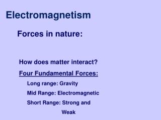
Electromagnetism. 22. Electromagnetism Content 22.1 Force on a current-carrying conductor 22.2 Force on a moving charge 22.3 Magnetic fields due to currents 22.4 Force between current-carrying conductors Learning Outcomes Candidates should be able to:

Electromagnetism
E N D
Presentation Transcript
Electromagnetism • 22. Electromagnetism • Content • 22.1 Force on a current-carrying conductor • 22.2 Force on a moving charge • 22.3 Magnetic fields due to currents • 22.4 Force between current-carrying conductors • Learning Outcomes • Candidates should be able to: • (a) show an appreciation that a force might act on a current-carrying conductor placed in a magnetic field. • (b) recall and solve problems using the equation F = BIlsinθ, with directions as • interpreted by Fleming's left-hand rule. • (c) define magnetic flux density and the tesla. • (d) show an understanding of how the force on a current-carrying conductor can be used to measure the flux density of a magnetic field using a current balance.
(e) predict the direction of the force on a charge moving in a magnetic field. • (f) recall and solve problems using F = BQvsinθ. • (g) sketch flux patterns due to a long straight wire, a flat circular coil and a long • solenoid. • (h) show an understanding that the field due to a solenoid may be influenced by the presence of a ferrous core. • (i) explain the forces between current-carrying conductors and predict the direction of the forces. • (j) describe and compare the forces on mass, charge and current in gravitational, electric and magnetic fields, as appropriate.
Electromagnets • An electromagnet is a coil which can produce a magnetic field when a current passes through it • Electromagnets are temporary magnets formed due to the flow of current through the material. • The strength of an electromagnet can be increased by • Increasing the current • Increasing the number of turns ie length of conductor • The use of a soft-iron core
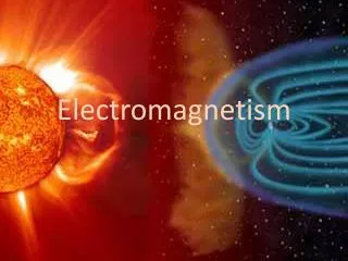
Action at a Distance Explained • Although two magnets may not be touching, they still interact through their magnetic fields. • This explains the ‘action at a distance’, say of a compass.
Physics of electromagnets • A ferromagnetic material is characterized by numerous tiny crystals each of which has one or more domains. • An elementary magnet resides in each domain. In the un-magnetized state, the elementary magnets are arranged randomly. • When subjected to a magnetic field, the elementary magnets line up with the external field. • Strong exchange forces now bind the elementary magnets together within each domain. Because they are all parallel, they give rise to a very strong field. • When a current is passed through a coil wound round a ferromagnetic material, it sets up a magnetic field tending to align the elementary magnets in the domains in the same direction resulting in a stronger field making it into an electromagnet
Uses of electromagnets • Electric bells • Electromagnetic relays • Telephone earpiece • Electromagnetic crane • Factory robots • Cassette recorders • Magnetic levitation trains
The motor effect • If a conductor is placed between magnetic poles and a current is passed through the conductor, the magnetic fields of the current carrying conductor and the magnet may interact causing forces between them • The existence of force can be demonstrated with an apparatus like on pg 321 fig 12.18 Physics by Chris Mee where a strip of aluminium foil is held loosely between the poles of a horseshoe magnet so that the foil is at right angles to the magnetic field • When the current is switched on, the foil jumps and becomes taut showing that a force is acting on it. This force is known as the electromotive force and the direction of the force depends on the directions of the magnetic field and of the current • This phenomenon is known as the motor effect or the catapult effect
Direction of the force on a current carrying conductor in a magnetic field • When a current carrying wire is placed in a magnetic field, a force will act on the wire, causing the wire to move or to turn • Direction of the force acting on the wire can be determined using Fleming's left-hand rule • Fleming's LH Rule • First finger is the direction of the magnetic field • Second finger points in the direction of the current • Thumb shall point in the direction of the force or motion
Magnitude of the force on a current carrying conductor in a magnetic field - Current balance • The magnitude of the electromotive force may be determined or investigated using a ‘current balance’ – pg 322 fig 12.20 Physics by Chris Mee • Variation of current Ileads to the conclusion that the electromotive force is directly proportional to the current • Variation of the length of the wire L in the magnetic field leads to the conclusion that the electromotive force is proportional to the length of the wire in the magnetic field • By varying the angle bewteen the wire and the direction of the magnetic field, the force is found to be proportional to sin θ • Hence F α IL sin θ leading to F = BIL sin θ where B is a constant which depends on the strength of the magnet. The stronger the magnet the greater the value of B • For a long straight conductor carrying unit current at right angles to a uniform magnetic field, the magnetic field strength B is numerically equal to the force per unit length of the conductor in the field ie F/L = BI sin θ
Magnetic field strength and tesla • Magnetic field strength B is usually referred to as magnetic flux density which is measured in SI unit of tesla (T) • An alternative name for magnetic field strength is the weber per square metre, Wb m-2 • One tesla is defined as the uniform magntic flux density which acting normally to a long straight wire carrying a current of 1 ampere, causes a force per unit length of 1 N m-1 on the conductor • Since on rearranging, B = F/(ILsin θ) , the tesla may also be expressed as N m-1 A-1 • Since B involves a force which is a vector quantity, hence magnetic flux density is also a vector quantity • From F = BIL sin θ,the force is a maximum when is θ is 90°i.e. the current and magnetic field are perpendicular to each other • B sin θ can be sometimes thought of as being the component of the magnetic flux density which is at right angles or normal to the conductor
Estimates of magnetic flux density • The tesla is a large unit of measure • A strong magnet may have a magnetic flux density of a few teslas between its poles • The magnetic field strength of an MRI is in the region of 7 teslas • The magnetic field strength due to the Earth in the UK is about 44 μT at an angle of 66° to the horizontal
Exercise • The horizontal component of the Earth’s magnetic flux density is 1.8 x 10⁻⁵ T. the current in a horizontal cable is 150 A. Calculate for this cable • a) the max force per unit length • b) the min force per unit length • In each case state the angle between the cable and the magnetic field • Ans: • 2.7 x 10⁻³ N m-1, 90° • 0, 0°
Force Between Two Conductors • Parallel conductors carrying currents in the same direction attract each other • Parallel conductors carrying currents in the opposite directions repel each other
Force between parallel conductors • Since a current carrying conductor has a magnetic field around it, if a second current carrying conductor is place near and parallel to the first, this second conductor will be in the magnetic field of the first and hence by the motor effect will experience a force • By a similar reasoning, the first conductor will also experience a force • By Newton’s III law, these forces will be equal and opposite • Experiment shows that if the currents are in the same direction. The 2 wires move towards each other, and if they are in opposite directions they move apart from each other • Can confirm using Fleming’s LH rule
Uses of the turning effect of the force • A moving coil meter • Consists of a rectangular copper coil with many turns of wires in the magnetic field of a permanent magnet • Can be used to measure current, voltages etc • when a current I is passed through a rectangular conducting coil of N turns suspended in a strong magnetic field B, a torque T acts on the coil giving the coil a deflection through an angle . • the torque is balanced by an opposing spring torque of c where c is the spring's elastic characteristics. • T = BANI = c where A is the cross sectional area of the coil.
The moving-coil loudspeaker • are widely used in radio receivers, televisions or public address systems that apply the principle of a current-carrying conductor placed in a magnetic field. • When an alternating current of the same frequency as the sound flows continuously in the speed coil, a mechanical force acts on the coil. • So the coil vibrates along its axis at a frequency equal to the audio-frequency alternating current flowing through it. The coil and cone vibrate at the same frequency and produce oscillations in the large mass of air in contact with the cone.
A direct current motor • Consists of a rectangular coil which is free to move in a U-shaped permanent magnet • Together with a commutator and carbon brushes powered by a power supply • Has a catapult effect
Defining Ampere and Coulomb • The force between parallel conductors can be used to define the Ampere (A) • If two long, parallel wires 1 m apart carry the same current, and the magnitude of the magnetic force per unit length is 2 x 10⁻⁷ N/m, then the current is defined to be 1 A • The SI unit of charge, the Coulomb (C), can be defined in terms of the Ampere (A) • If a conductor carries a steady current of 1 A, then the quantity of charge that flows through any cross section in 1 second is 1 C
Comparing and summarising the effects of fields • There are close analogies between gravitational and electric fields but in some ways they behave very differently • Because masses always attract each other, a mass placed in a gravitational field will always move in the direction of the field, from a position of higher potential to a lower potential • Charges on the other hand will move in the direction of the electric field if positive (from a position of higher potential to a lower potential just like a mass in a gravitational field) or against the direction of the field (and from a low potential to a high potential) if negative • The field strength for both gravitational and electric fields obey an inverse square law relationship and the potential obeys a reciprocal relationship with distance from the source of the field • However a stationary charge in a magnetic field is unaffected, whereas a moving charge experiences a force given by F = Bqv sin θ and the direction of the force is given by Fleming’s LH rule • Finally, a current-carrying conductor in a magnetic field does not experience a force if the conductor is parallel to the field direction, but for all other directions it experiences a force given by F = Bqv sin θ and the direction is again determined by Fleming’s LH rule