Download
1 / 16
160 likes | 314 Vues
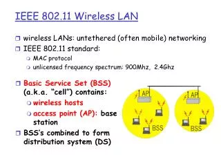
Removing Hidden Nodes in IEEE 802.11 Wireless Networks. Libin Jiang Sep 23th, 2004. Outline. HN and HN-induced problems Previous research HN-Free Design (HFD) Performance Evaluation Eliminating HN-induced problems Future work. Hidden-Node (HN).

E N D
Removing Hidden Nodes in IEEE 802.11 Wireless Networks Libin Jiang Sep 23th, 2004
Outline • HN and HN-induced problems • Previous research • HN-Free Design (HFD) • Performance Evaluation • Eliminating HN-induced problems • Future work
Hidden-Node (HN) • A link with sender node A and receiver node B is said to suffer from HN if the data exchange from A to B may fail because A and the sender of another potentially interfering link cannot sense each other. A network is said to suffer from HN if any of its link suffers from HN. • Examples • Link 1 suffers from HN S3; • Link 2 suffers from HN S1; • HN-induced problems • Unfairness • Throughput degradation and Re-routing instability
Previous research • A lot. • [1] addressed HN-induced unfairness problem. This work, like many others, does not remove HN and instead focuses on eliminating one of its negative effects. • Reference [2] provided a “node-based” analysis of HN. It was argued that when the physical carrier sensing range (CS) is larger than the transmission range (dmax) plus the maximum interference range (IRmax), HN can be removed. This is not always true according to our “link-based” analysis. • [1] X. Huang, B. Bensaou, “On Max-min Fairness and Scheduling in Wireless Ad-Hoc Networks: Analytical Framework and Implementation”, ACM MobiHoc’02, Long Beach, USA, Oct. 2001. • [2] K. Xu, M. Gerla, S. Bae, “How Effective is the IEEE 802.11 RTS/CTS Handshake in Ad Hoc Networks?”, IEEE GLOBECOM '02, Vol. 1 , pp. 17-21, Nov. 2002.
Outline • Definition of HN and HN-induced problems • Previous research • HN-Free Design (HFD) • Performance Evaluation • Future research
Hidden-node Free Design (HFD)--basic access mode • Assumptions and definition: • All nodes’ transmission power is fixed at Pt • The function P(.) is the received power as a function of distance.Assume P(.) is a decreasing function of distance (usually true except indoor environments). • Let d be the distance of a link. dmax is the maximum distance of a link (or “Transmission Range”), CS is the physical carrier-sensing range, • Ct : Capture threshold (e.g. 10dB)
Hidden-node Free Design (HFD)--basic access mode • (Requirement 1). Receiver Restart Mode (RS)[1]: • [1] This mode can be enabled in some commercially available 802.11 chips. Also called “capture mode”. • [As before] A node with RS that has carrier-sensed a transmission in progress should not initiate a new DATA transmission of its own. • [As before] When a node is in the process of listening one packet, and a new packet comes in. If its power is sufficiently smaller (1/Ct times) than the first one, the node will successfully decode the first packet and ignore the second one. • [RS mode] However, if the power of the new packet is sufficiently larger that the previously sensed packet (say, with Ct times the power of the previous packet), the receiver will switch to receive the stronger packet, and be able to receive it correctly. If the new signal is an 802.11 DATA targeted for it, the node will reply with an ACK after a SIFS interval, whether the medium is busy or not. • RS mode ensure that packet reception is based on power, instead of the order of arrival.
Interference Range • Interference Range (IR) • P(d)/P(IR)=Ct • Max Interference Range (IRmax) satisfied • P(dmax)/P(IRmax)=Ct • The second requirement for Hidden Node-free (the senders of two interfering links need to hear each other): • CS >= 2dmax + IRmax • A corresponding HFD can be found for networks operated with the RTS/CTS mode. The sufficiency condition in (b) needs to be modified slightly.
A brief proof of sufficiency • Notice that each link is two-way traffic: DATA and ACK—need to examine |Si-Sj|, |Ri-Rj|, |Si-Rj|, |Sj-Ri| • If |Si-Sj|>CS>=2dmax+IRmax, then according to triangle inequality, • |Ri-Rj|>=|Si-Rj|-|Si-Ri|>=|Si-Sj|-|Sj-Rj|-|Si-Ri|>CS-2dmax>=IRmax • Similarly, |Si-Rj|>IRmax;|Sj-Ri|>IRmax. Obviously |Si-Sj|>IRmax • Also, di<dmax and dj<dmax. So, collisions are impossible.
Outline • Definition of HN and HN-induced problems • Previous research • HN-Free Design (HFD) • Performance Evaluation • Future work
Elimination of HN Performance Problems-- a Performance Evaluation of HFD • A chain topology • The nodes are spaced by 140m • w/o HFD, CS = 550m, dmax = 250m as default in NS2 • with HFD, CS= 550m, dmax=CS/3.78=145m
Other parameters • The data rate of 802.11 is set at 11Mbps • Payload on each packet: 1460 Bytes • Two-ray ground propagation model is adopted with alpha=4. • Crt and Ct, are set to 10dB. • Routing protocol: AODV
Elimination of HN Performance ProblemsTCP unfairness • Traffic: As in (b), TCP 1 is from node 1 to 3, and TCP 2 is from node 6 to 4. TCP 1 starts earlier at 3.0 sec, and TCP 2 starts at 10.0 sec. • w/o HFD HFD
Elimination of HN Performance ProblemsRe-routing Instability • Traffic: as in (a), a UDP flow is from node 1 to node 12 (11 hops). • Re-routing instability is triggered by excessive packet collisions introduced by hidden nodes (which is mistaken for route unavailability) • Once HN is gone, instability is gone.
Future work • HFD’s effects on network capacity and connectivity in different topologies. • In the above simulation (with CS a constant), dmax is reduced in HFD. It means the network connectivity is reduced. The tradeoff of connectivity needs quantitatively study. • Exposed-node problem (Disallowing simultaneous transmissions which are collision) • HFD is a set of sufficient conditions for HN-free operation, but not necessary conditions. • In other words, HFD may be over-conservative in particular scenarios. • Need to further remove EN.