Download
1 / 29
290 likes | 460 Vues
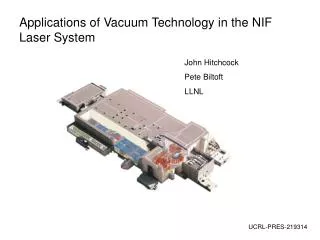
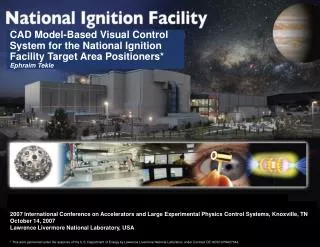
CAD Model-Based Visual Control System for the National Ignition Facility Target Area Positioners* Ephraim Tekle. 2007 International Conference on Accelerators and Large Experimental Physics Control Systems, Knoxville, TN October 14, 2007 Lawrence Livermore National Laboratory, USA.

E N D
CAD Model-Based Visual Control System for the National Ignition Facility Target Area Positioners* Ephraim Tekle 2007 International Conference on Accelerators and Large Experimental Physics Control Systems, Knoxville, TN October 14, 2007 Lawrence Livermore National Laboratory, USA * This work performed under the auspices of the U.S. Department of Energy by Lawrence Livermore National Laboratory under Contract DE-AC52-07NA27344.
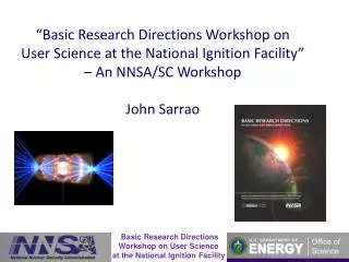
NIF concentrates all the energy in a football stadium-sized facility into a mm3 NIF is 94% complete, on schedule and budget
Symmetry & nomenclature National Ignition Facility NIF is a 192 beam laser organized into quads, bundles and clusters with a 10m diameter chamber Target Chamber Quads are the basic building blocks of a NIF experiment, 4 beams with same pulse shape and time delay. Each quad enters the chamber through the final optic assemble. Laser Ports
60,000 control points are installed in over 6,000 line replaceable units ICCS is deployed on 850 front-end processors, servers, and workstations A CORBA-based software framework was developed to deliver 1.8M SLOC 192 beams precisely aligned on target to 10 microns over a 300-meter optical path The Integrated Computer Control System (ICCS) orchestrates complex automated shots Main Control Room Shots fired every few hours culminate in a nanosecond laser pulse in lock-step with diagnostics timed to 30 picoseconds
Ten target and diagnostic positioners are precision aligned for each shot Diagnostics insertion manipulator (DIM) Streak X-ray imager (SXI) Alignment sensor positioner Target positioner Future DIM Optics damager inspection positioner DIM Cross-chamber reference system (CCRS) SXI CCRS DIM Cryo-Target positioner
10 meters The target positioner (TARPOS) inserts the mm-scale fuel capsule with five degrees-of-freedom
The alignment sensor views the target for precision alignment
Diagnostic instruments manipulators (DIM) position physics packages at chamber center Four DIMs precision align a diverse suite of diagnostic instruments
Target Chamber Upper Beam Ports The seven-floor target bay contains the vacuum chamber, final optics system, and target diagnostics
Each experiment requires careful coordination of the motion control system • Limited chamber access requires remote control and sensing • Positions maintained to accuracies of 10 microns • Varied 3D geometries and alignment scenarios • Complex motion sequences involving multiple devices • Absolute encoder and video feedback • Potential collisions must be avoided A CAD model-based control system with integrated video feedback meets these requirements
Collision avoidance protects positioners that reach 6 meters into the chamber Positioner Interference Matrix Target Alignment Sensor Cryo Target 1 Cryo Target 2 Diagnostics 1 Diagnostics 2 X-ray Imager 1 X-ray Imager 2 Optics Inspection
Situational awareness provided by the surveillance cameras is less than ideal Wide Field-of-View Narrow Field-of-View Chamber Wall High viewer magnification limits the field-of-view to a small central region
Camera views of the chamber interior Wide FOV Narrow FOV
Collision-free positioner routes are calculated using model-based analysis and tracking tools • Pro/ENGINEER* • CAD tool used to design NIF’s mechanical hardware • Leveraged to derive the control system model • DIVISION MockUp* • 3D simulation of the chamber and all positioners • Based on experimental set up • Used for real-time controls during operations • Live visualization of positioner operation • Delivers sub-millimeter accuracy • High-precision servo motors with encoders provide hardware feedback • Determines distances between points or/and positioners • Calculates collision free routes * Pro/ENGINEER and DIVISION MockUp are a registered trademark of Parametric Technology Corporation (PTC)
The 3D model “sees” the chamber mechanical arrangement at all times
3D simulation and analysis tool coded in Java proved the model-based concept
Simulation integrity is verified in real-time by comparison to the view generated by MockUp Live-video Semi-transparent overlay from MockUp
Visual assisted control • Calibrated video • Virtual 3D axes are defined using cross-coupling matrices • Video views are calibrated to these axes • Video integrated control • Calibrated videos provide a live-video integrated control by dragging movement commands on the screen • Operator aids • Live-video overlays • Alignment markers • Zoom, etc.
Movement commands are “dragged” across the live video display using calibrated views • Reference point and transformation matrix • Maps any point (x,y) in the camera coordinate system to (x,y,z) in chamber coordinate system • Scale and rotation factors • Maps video pixels (x,y) to positioner coordinate system • 3D virtual-axes • Defined along camera field-of-view using cross-coupling matrices (x,y) x 865 mm 880 mm 750 mm
Routing is analogous to driving directions given by Google Maps x x x Positioner route finding x Segment (3D axis) x Pause points x GoogleTM Map
The offline test lab integrates special hardware simulators and cameras • Hardware-based testing • Multi-axis encoded hardware simulators on an optics table • Calibrated cameras • PLC motor end-of-travel monitoring and shut-down system • Configured to mimic the NIF target chamber • Software-based testing • Emulated virtual positioners • Provides for multiple concurrent tests The test lab ensures software quality, assesses usability, and helps train operators
Hardware-based testing is supported by five-axis positioner simulators that have the same range of motion as the real positioners
Test Lab Calibrated video cameras Simulator undergoing acceptance tests
Conclusion • Enhanced real-time video feedback provides operators with metrology and controls in real physical dimensions • Model-based visualizations provide a complete control environment in support of complex operations in the limited access chamber • Model validation assures the system accurately represents reality • Automated controls ensure interference-free and repeatable coordinated motion sequences • Status • Video-assisted controls are deployed to NIF • CAD model-based system is on schedule for delivery next year