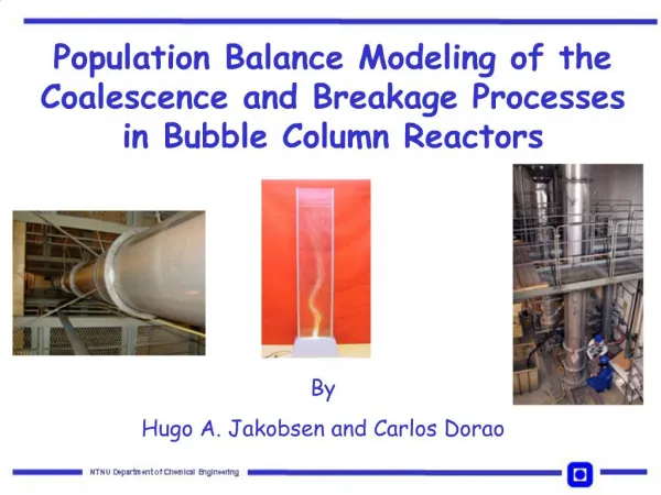
Bubble Column Reactors
Bubble Column Reactors. Quak Foo Lee Department of Chemical and Biological Engineering The University of British Columbia. Topics Covered. Bubble column fundamentals Type of bubble columns Gas Spargers Bubble flow dynamics CFD Modeling Experiments vs. Simulations. Introduction .


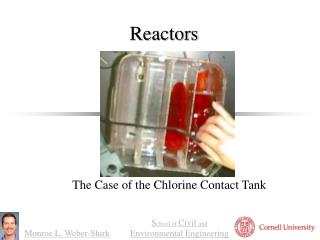
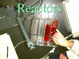
Bubble Column Reactors
E N D
Presentation Transcript
Bubble Column Reactors Quak Foo Lee Department of Chemical and Biological Engineering The University of British Columbia
Topics Covered • Bubble column fundamentals • Type of bubble columns • Gas Spargers • Bubble flow dynamics • CFD Modeling • Experiments vs. Simulations
Introduction • Bubble columns are devices in which gas, in the form of bubbles, comes in contact with liquid. • The purpose may be simply to mix the liquid phase. • Substances are transferred from one phase to the other
Bubble Columns • Gas is sparged at the bottom of the liquid pool contained by the column. • The net liquid flow may be co-current or counter-current to the gas flow direction or may be zero. • Spargers, like porous plates, generate uniform size bubbles and distribute the gas uniformly at the bottom of the liquid pool.
Bubble Column Co- current Counter- current
Type of Bubble Columns • Simple bubble column; B) Cascade bubble column with sieve trays; • C) Packed bubble column; D) Multishaft bubble column; • E) Bubble column with static mixers
Gas-Liquid Mixing A) Bubble column; B) Downflow bubble column; C) Jet loop reactor
Gas Distributions • The gas is dispersed to create small bubbles and distribute them uniformly over the cross section of the equipment to maximize the intensity of mass transfer. • The formation of fine bubbles is especially desirable in coalescence-hindered systems and in the homogeneous flow regime. • In principle, however, significant mass transfer can be obtained at the gas distributor through a high local energy-dissipation density.
Static Gas Spargers Dip tube Perforated plate Perforated ring Porous plate
Fluid Dynamics • Rising gas bubbles entrain liquid in their wakes. • As a rule, this upward flow of liquid is much greater than the net liquid flow rate. • Because of continuity, regions therefore exist in which the liquid is predominantly moving downward.
Fluid Dynamics Radial distribution of liquid velocity in a bubble column
Bubble Size Sauter diameter dbS (mean bubble diameter, calculated from the volume to surface ratio) This formula is based on Kolmogorov's theory of isotropic turbulence.
Bubble Size Distribution (BSD) • Narrow BSD • For bubble columns with relatively low gas volume fraction. • In homogeneous regime. • Wide BSD • As gas velocity and therefore, gas volume fraction increases, a heterogeneous or churn-turbulent regime sets in.
Gas Holdup • Gas holdup is one of the most important operating parameters because it not only governs phase fraction and gas-phase residence time but is also crucial for mass transfer between liquid and gas. • Gas holdup depends chiefly on gas flow rate, but also to a great extent on the gas – liquid system involved.
Gas Holdup • Gas holdup is defined as the volume of the gas phase divided by the total volume of the dispersion: • The relationship between gas holdup and gas velocity is generally described by the proportionality: • In the homogeneous flow regime, n is close to unity. When large bubbles are present, the exponent decreases, i.e., the gas holdup increases less than proportionally to the gas flow rate.
Interphase Forces • Drag force • Resultant slip velocity between two phases. • Virtual mass force • Arising from the inertia effect. • Basset force • Due to the development of a boundary layer around a bubble. • Transversal lift force • Created by gradients in relative velocity across the bubble diameter, may also act on the bubble.
Bubble Column Modeling Mass transport mixing Fluid properties Reaction Fluid Dynamics Enhancement Phase distribution transfer resistance Mass transfer Heat transfer Limitation Gas hold-up Interfacial area driving force mixing Bubble recirculation Bubble breakage And coalescence Fluid properties Turbulence shear stress terminal velocity residence time
CFD Modeling of Bubble Columns • Eulerian-Lagrangian approach • To simulate trajectories of individual bubbles (bubble-scale phenomena) • Eulerian-Eulerian approach • To simulate the behavior of gas-liquid dispersions with high gas volume fractions (e.g. to simulate millions of bubbles over a long period of time)
Simulation Objective • Unsteady, asymmetric • To avoid imposing symmetry boundary conditions • Two-dimensional • Consider the whole domain • Three-dimensional • Use a body-fitted grid, or • Use modified conventional axis boundary conditions to allow flow through the axis
When to use 2D Simulation? • Estimate liquid phase mixing and heat transfer coefficient. • Predict time-averaged liquid velocity profiles and corresponding time-averaged gas volume fraction profiles. • Evaluate, qualitatively, the influence of different reactor internals, such as drat tubes and radial baffles, on liquid phase mixing in the reactor.
When to use 3D Simulation? • Capture details of flow structures. • Examine the role of unsteady structure on mixing. • Evaluate the size and location of draft tube on the fluid dynamics of bubble column reactors.
Simulation Consideration • For column walls, which are impermeable to fluids, standard wall boundary conditions may be specified. • Use symmetry when long-time-averaged flow characteristics is interested. • When the interest is in capturing inherently unsteady flow characteristics, which are not symmetrical, it is essential to consider the whole column as the solution domain. • Overall flow can be modeled using an axis-symmetric assumption.
2D Bubble Column Open to surroundings Overhead pressure Liquid drops may Get entrained in overhead space Ptop Gas-liquid Interface (may not be flat) Gas-liquid Dispersion (gas as dispersed phase) Hydrostatic head above the sparger P0 Sparger Plenum Ps Only gas phase P0 = Ptop + Ph Gas
First bubble flow region Descending flow region Descending flow region Vortical structures 2D 3D 2D and 3D ‘Instantaneous' Flow Field Source: http://kramerslab.tn.tudelft.nl/research/topics/multiphaseflow.htm
Verification and Validation • Scale-down for experimental program. • Experiments are carried out in simple geometries and different conditions than actual operating conditions. • Available information on the influence of pressure and temperature should be used to select right modelfluids for these experiments. • Detailed CFD models should be developed to simulate the fluid dynamics of a small-scale experimental set-up under representative conditions. • The computational model is then enhanced further until it leads to adequately accurate simulations of the observed fluid dynamics. • The validated CFD model can then be used to extrapolate the experimental data and to simulate fluid dynamics under actual operating conditions.
Experiments Meandering motions Lateral movement of the bubble hose in the flat bubble column (gas flow rate 0.8 l/min) Becker, et al., Chem. Eng. Sci. 54(12):4929-4935 (1999)
Simulation and Experiment t = 0.06s t = 0.16s t = 0.26 s t = 0.36 s Simulation and experimental results of a bubble rising in liquid-solid fluidized bed. Fan et al. (1999)
References: • Becker, S., De Bie, H. and Sweeney, J., Dynamics flow behavior in bubble columns, Chem. Eng. Sci., 54(12):4929-4935 (1999) • Fan, L.S., Yang, G.Q., Lee, D.J., Tsuchiya, K., and Lou, X., Some aspects of high-pressure phenomena of bubbles in liquids and liquid-solid suspensions, Chem. Eng. Sci., 54(12):4681-4709 (1999)