IGCC
IGCC. Reliance Industries Limited. Clean Coal Technology Conference 10 th November,2009 - PDPU, Gandhinagar. By. Parthasarathi Deb. Contents. IGCC Salient features. History of Gasification: Global & Indian. Types of Gasifiers. Reliance Strategy for Petcoke Utilisation.

IGCC
E N D
Presentation Transcript
IGCC Reliance Industries Limited Clean Coal Technology Conference 10th November,2009 - PDPU, Gandhinagar By Parthasarathi Deb
Contents IGCC Salient features History of Gasification: Global & Indian Types of Gasifiers Reliance Strategy for Petcoke Utilisation Project formulation for Petcoke Gasification Process of Evaluation Emerging Technologies
Integrated Gasification and Combined Cycle (IGCC) Gasification Island Air Separation Unit (ASU) Power Island IGCC: Integration among the various Islands of Technology.
Block Flow Diagram of IGCC & Integration options GASIFICATION ISLAND Slag Coal Heat Recovery Sulphur Coal Preparation Gasification Gas Cleaning Fly Ash N2 O2 Waste N2 Clean Gas Air Air Separation Unit (ASU) Gas Turbine Air Water Air Heat Recovery Steam generator (HSRG) Feed water Steam Water / Steam integration Air side ASU-CC integration Steam Turbine N2 side ASU-CC integration COMBINED CYCLE
Existing Coal-based IGCCs Tampa (Florida)
Existing Coal-based IGCCs Buggenum (Netherlands)
Existing Coal-based IGCCs Wabash (Indiana)
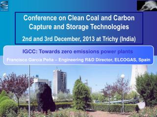
Existing Coal-based IGCCs Puertollano (Spain)
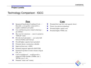
Features of IGCC Technology Efficiency:
Features of IGCC Technology Environment:
Features of IGCC Technology Environment: 1. SOx , NOx and Particles: SOx , NOx and particulate emissions are comparable to or less than those obtained in a combined cycle using Natural Gas (NGCC). 2. Greenhouse effect gas CO2 : CO2 emission is reduced by 20% in IGCC over conventional boiler base power plant. CO in syngas can be converted to CO2 and production of Hydrogen can be increased. Thus CO2 can be captured directly using regular commercial process at a higher pressure than extracting it from combustion gases from conventional PC plant or NGCC plant. 3. Water consumption: Specific consumption of water for the operation of IGCC plant is approx. half that of conventional plant using gas cleaning system.
Features of IGCC Technology Environment: 4. Other contaminants : Chlorine , Mercury, Heavy metals: In IGCC operation, Chlorine compounds are extracted from Gas by washing with water. Heavy metals are almost entirely captured in the slag which is a vitrified, non leachable, inert solid. Mercury can be removed by absorption on a bed of active carbon for IGCC at a cost of 1/12 that of PC power plant. 5. Solid by products: Sulphur is recovered in a pure elemental state or as sulphuric acid. Solid waste (slag) can be disposed as by products for manufacturing of ceramic material, fiber glass, filling roads, manufacturing of cements, roof tiles or bricks.
Features of IGCC Technology Fuel-multiple choice: IGCC / POX : 1. Fossil Fuel:- Natural gas Petroleum coal 2. Alternative fuels:- Petroleum coke Biomass and waste products The security of supply of fuel, stability in prices of fuel and multiplicity in choice of fuel, IGCC Technology has clear cut edge over other technology / process for power generation.
Features of IGCC Technology Global Situation:
Features of IGCC Technology Global Situation:
Features of IGCC Technology Investment Cost: $/kw 1,500 1000 500 0 1997 2015 2000 2010 Forecast development evolution IGCC power plants costs ($/kw)
Features of IGCC Technology Cost Comparison among IGCC, PC and NGCC Power plant:
Features of IGCC Technology Cost Comparison among IGCC, PC and NGCC Power plant: Coal price = 1.38 €/MMBtu Gas price = 3.74 €/MMBtu
History of Gasification • PERIODTECHNOLOGY • Before 1700 Major fuels were Wood and Charcoal • 1700-1750 Industrial revolution – Coal as fuel • 1800-1900 Coal Pyrolysis – Town gas supply • Water gas, Producer Gas • 1920 Cryogenic air separation – Oxygen replaces air • 1926 Winkler Fluidized Bed Gasifier • 1931 Lurgi Moving Bed Gasifier • Koppers-Totzek Entrained Flow Gasifier • 1950s Texaco and Shell develop Oil Gasification
History of Gasification PERIODTECHNOLOGY 1970s Oil crisis 1973 Texaco develops Slurry Process for Coal Gasification 1974 Shell and Koppers-Totzek Pressure Gasification JV 1981 High Temperature Winkler Gasification 1984 Lurgi Slagging Gasifier (together with British Gas) 1999 Shell/Krupp-Uhde develops Pressurised Entrained Flow (PRENFLO) Gasifier Beyond 2000 Shell Gasification, GE Quench/PHR/FHR, Siemens, Chinese, GPE, Plasma, Headwaters
Gasification – Indian Context PERIODTECHNOLOGYFEEDLOCATION 1940s Wood Gasification Wood FACT - Cochin 1945-1950 Lurgi Fixed Bed Coal Sindri 1960s Winkler Fluidized Bed Lignite Neyveli 1960s Texaco Naphtha FACT - Cochin 1970s Krupp-Koppers Coal Ramagundam Entrained Bed Atm. Talcher 1970s Shell Fuel oil Sindri 1980s Shell Fuel oil NFL - Bhatinda, Panipat, Nangal 1980s Texaco Fuel oil GNFC - Bharuch
What Is Gasification? • Conversion of any carbonaceous fuel to a gaseous product with a useable heating value. • The feed for Gasification can be • Gas (e.g., Natural gas) • Liquid (e.g., Light or Heavy oils) • Solid (e.g., Petroleum Coke, Coal, Lignite or Biomass).
Types of Gasifiers 1) Moving/Fixed bed e.g., Lurgi Counter-current Co-current 2) Fluidized bed e.g., Winkler/KBR/U-GAS 3) Entrained flow Dry pulverized solid fuel e.g., Shell/Prenflo/Siemens Fuel slurry e.g., GE/Conoco-Philips Atomized liquid fuel e.g., GE/Shell
Temperature Profile of Gasifiers MOVING BED GASIFIER(400-1100 0 C, 10 to 100 bar) FLUIDIZED BED GASIFIER(800 – 10500C, 10 to 25 bar) ENTRAINED FLOW GASIFIER(1200-16000C, 25 to 80 bar)
Background Story of Petcoke Usage • First Refinery at Jamnagar started up in Q4’99. Petcoke production ~ 8500 TPD • During project engineering phase several options for petcoke usage were discussed: • Thermal power plant – CFBC Boiler + STG • Petcoke gasification to generate H2 for refinery. Back up of coal feed during start up • Storage of petcoke during intervening period between start up of refinery and proposed units above • Focused effort for marketing of petcoke – National + International Customers • Marketing efforts were so successful, that we didn’t pursue any of the other options.
Future Petcoke Scenario • Second Refinery at Jamnagar start up on Q4’08 • Expected petcoke production: ~9000 TPD • Total Reliance petcoke generation: ~6.5 MMTPA • Expected additional generation of petcoke in India by 2012: ~10 MMTPA • This far exceeds captive demand of ~4 MMTPA • Surplus petcoke is available • Reliance considers petcoke gasification as opportunity for value addition
Key Drivers for Petcoke Gasification • Transform “Jamnagar” into “bottomless” refinery • Exploit price delta between natural gas and petcoke • Replace natural gas with syngas, to manage the supply risk • Insulate the Jamnagar refinery from future energy cost escalation • Pursue reduction in GHG through possible CO2 capture and sequestration
Project Scope • PETCOKE QTY - 17500 TPD (Dry Basis) 19000 TPD (As recd. Basis) • OXYGEN-18,000 TPD • SYN. GAS PRODUCTION - 40,000 TPD 2/3rd FOR POWER 1/3rd FOR HYDROGEN/ CHEMICALS • POWER GENERATION - 1140 MW • HYDROGEN GENERATION - 900 TPD
Typical Fuel Composition * For reference of comparison only
Why Entrained Flow Gasifier? • Ability to handle variety of solid fuels • High throughput because of high reaction rates/temperature • Opportunity for heat recovery • High carbon conversion • Syngas free of oils and tars • Low methane production
GE Quench Gasifier – Slurry Feed 14500C 10000C 5500C 2800C 3000C 1 • Steel Pressure Shell • Insulation Layer • Castable Layer • Hot-face Refractory 2 3 4
13000C 8000C 5000C 500C 2000C 1 2 3 4 5 6 7 8 Shell Membrane Walled Gasifier 16500C Syngas Cooler • Flowing Slag Layer • Solid Slag Layer • High Alumina Refractory Material • Metallic Studs (Incolloy) • Membrane Tube Wall • Free Space • Refractory Lining on Pressure Vessel • Pressure Vessel
Process Flow STG HRSG Flue gases Power N2 Power GT Air Steam ASU SRU O2 H2S Sulphur Air Gasifier Gas Cleaning & Cooling AGR Grinding Steam CO2 Capture Feed Coke Slag + Fine Ash To SRU AGR CO2 Sour Shift AGR H2S Sweet Shift PSA Hydrogen
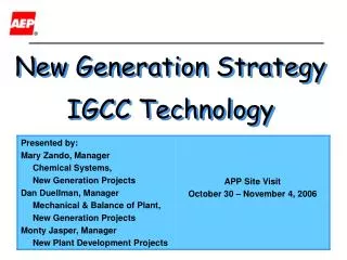
Retrofitting of existing assets Retrofittings of GT (Frame 6 & Frame 9) for Syngas firing: • Piping: • Syngas • N2 Purge • N2 / steam • Controls • MK 6 • Software • Instrumentation (valves / flow meter) • Combustion • Fuel Nozzle • Liners • Syngas Skid • Syngas injection • Air Extraction (Optional) • N2 injection ( Optional) • Compartment modification • Off base enclosure • CFD modeling • Hazardous gas detection system
Gasification: Ultimate Product Flexibility Power & Steam Carbon Source Iron Reduction Fuel/Town Gas Gasification Naptha Fischer- Tropsch Liquids Ammonia & Urea Waxes Synthesis Gas H2 Diesel/Jet/Gas Fuels Methanol Dimethyl Ether Synthetic Natural Gas Ethylene & Propylene Methyl Acetate Acetic Acid Acetate Esters Ketene VAM Oxo Chemicals Diketene & Derivatives Polyolefins Acetic Anhydride PVA
Process of Evaluation • Proposal from process licensors • Series of discussions with process licensors • Visit to plants of GE & Shell and discussion with plant operators: • LocationFeedstock GE • Coffeyville resources, USA Petcoke • Polk Power Plant, Tampa Coal + Petcoke • Eastman Chemical Company, Kingsport Coal • Sarlux IGCC, Cagliari Vacuum residue • Wison Chemical Co, Nanjing Coal • Sinopec Nanjing Chemical Industries Co, Nanjing Coal • Shanghai Coking and Chemical Company Coal • GNFC, Bharuch Fuel oil Shell • Nuon Power, The Netherlands Coal+ Biomass • Elcogas, Puertallano, Spain Coal + Petcoke • Yueyang Sinopec & Shell Coal Gasification Co Ltd, China Coal
Process of Evaluation (contd.) • Information and data available in the public domain. • CAPEX estimation based on: • PFD & sized equipment list provided by the licensors • Pre-engineering to estimate quantities of bulk materials • OPEX estimation for Jamnagar location • Personal experience of operating oil and coal gasifiers.