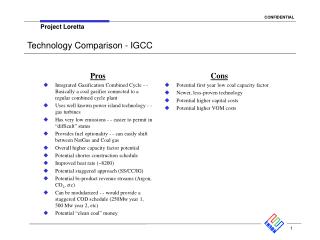
New Generation Strategy IGCC Technology
New Generation Strategy IGCC Technology. The American Electric Power System. 100 years in operation 36,000 MW generation capacity – more than 70% coal Largest generator of electricity in US Largest coal purchaser and consumer – over 70 million short tons (64 million metric tons) per year

New Generation Strategy IGCC Technology
E N D
Presentation Transcript
New Generation Strategy IGCC Technology
The American Electric Power System • 100 years in operation • 36,000 MW generation capacity – more than 70% coal • Largest generator of electricity in US • Largest coal purchaser and consumer – over 70 million short tons (64 million metric tons) per year • 39,000 miles (62,000 km) transmission • 7,900 miles (12,600 km) 230 – 765 kV • 200,000 miles (320,000 km) distribution • 5 million customers in 11 states • $11.9 billion annual revenue • $36.2 billion assets Source: AEP 2005 Annual Report Revenues: $14.5 billion Assets: $37 billion US customers: 5 million US employees: 22,000 Source: AEP 2003 Annual Report
AEP Today: The Need for New Generation • AEP is committed to providing reliable, affordable, and sustainable electricity to our 5 million customers. • AEP has not added base load capacity since 1991 (Zimmer conversion) • AEP will need approximately 1200 MW of additional generating capacity in our Eastern region by 2010 • AEP believes that Integrated Gasification Combined Cycle (IGCC) technology is the best choice for capacity additions in the East Revenues: $14.5 billion Assets: $37 billion US customers: 5 million US employees: 22,000 Source: AEP 2003 Annual Report
Site Selection & Evaluation Process • Where is the best site to build a new IGCC Power Plant in AEP East? • Site Study Team Established • Representatives from AEP • Third Party Consultant retained for study • Potential Sites Identified • AEP existing plants sites • AEP owned/controlled property • Fatal Flaw Analysis to narrow list • 15 sites identified for evaluation • Developed Ranking Criteria • Established Design Basis
Design Basis - Key Siting Parameters • 600 MW IGCC Unit (with option to expand to 1200 MW) • 2 x 2 x 2 x 1 Configuration • 2 Operating Gasifiers / Gas Cleanup Systems • 2 Combustion Turbines • 2 Heat Recovery Steam Generators • 1 Steam Turbine
Site Selection Ranking Criteria • Fuel Delivery • Distance from Rail or Barge • Alternate Transportation • Distance from Natural Gas Pipeline • Delivered Coal Cost Differential • Cooling Water • Distance from Adequate Water Source • Adequacy of Cooling Water Source • Land Use • Designated Parks & Recreation Areas • Existing Land Use • Existing Residences • Nearby Land Use • Habitat • Wetlands Impact Potential • Other Natural Habitats Impact Potential • Documented Presence of Threatened and Endangered Species • Site Topography • Topography and Size • Expandability • Distance from Waste Disposal • Flood Potential • Constructability • Air & Water – Environmental • Distance from Class I Areas • Dispersion Conditions • Existing Air Quality • Air Quality Non-Attainment Area • CO2 Sequestration - Third Party Desktop Study • Transmission • Distance from Transmission • Transmission Stability • Feasibility of 2 Unit Transmission plan
Site Selection Ranking Criteria • Weighting Factors • Scale of 1 - 10 • Rating Factors • Scale of 1 – 5 • Example below
Results • Top Sites by State • Mountaineer – West Virginia • Great Bend – Ohio • Carrs - Kentucky
Generating Technology Options: Integrated Gasification Combined Cycle (IGCC) Plants
Gasification Technology Options • Business Models of Various Technology Suppliers • Syngas over the fence • Technology owner provides capital investment and operating services • Cost of syngas may be tied to fuel cost, escalation, other factors • Also oxygen over the fence • Licensing • Technology owner provides equipment design and performance guarantees for equipment • Owner assumes risk of integrated unit performance • Turn key EPC with performance guarantees • Technology owner provides engineering and design of integrated unit and all components • Technology owner also assumes cost and schedule risk • Guaranty of total unit performance: inputs vs. outputs
Gasification Technology Options • Commercial Technology Choices • Slurry fed – Conoco, GE • Slurry fed technologies suited to high rank fuels • Dry fed – Shell • Better heat rate, longer injector life • Technology suited for lower rank subituminous coals as well as high rank fuels • Heat Recovery/Integration • Quench – GE • Chemical production applications • Radiant syngas cooler – GE, Conoco, Shell • Heat recovery for power generation in steam turbine • Convective syngas cooler – GE • Availability impact due to plugging – not selected for reference plant
Current Configuration – AEP East IGCC • Net output 621 MW, Heat Rate 8,890 Btu/kWh (2,240 kcal/kWh) • Target turndown to 40% of full load, and load following operation • Broad fuel specification (eastern bituminous coal, petcoke) • GE (formerly Texaco) Gasifiers • Two radiant + quench gasifiers – no spare • Operating pressure 625 psi (43 bar) • Turbine-Generators • Two GE 7FB combustion turbines - 232 MW each • Evaporative inlet cooling • Single steam turbine – 300 MW • Emissions Control Systems • Selexol acid gas removal system for sulfur (H2S) removal w/COS reactor • Activated carbon bed for mercury removal • Syngas moisturization, nitrogen diluent for NOx control • Space provisions for future polygeneration and CO2 capture
Gasifier/Radiant Syngas Cooler (RSC) • The gasifier operates at approximately 625 psi (43 bar) and 2550oF (1400oC) • Gasifier volume 1800 cubic ft (50.4 cubic meters) • The RSC generates high pressure steam by cooling the hot syngas from the gasifier from 2550oF to 1250oF (1400oC to 700oC). • The RSC vessel is lined with waterwall panels along the inside perimeter of the vessel as well as some in the radial direction. The steam is generated in the RSC and circulated to the external steam drum. • The RSC concept has been demonstrated at plants in Germany as well as Coolwater and Polk Power in the USA. The vessel is about 6 m in diameter and 30-40 m long. • The AEP RSC design is different than the Polk Power design because it has an internal water quench section at the vessel bottom which further cools the syngas at about 450oF (230oC).
Gasifier/Radiant Syngas Cooler (RSC) • When the gasifier load changes the oxygen to slurry ratio remains constant because the oxygen to carbon ratio is part of the control system. • The gasifier is connected to the RSC through a flange connection. The vessel heads and flanges are protected by the refractory lined transfer line. • The molten slag from the gasifier solidifies as it cools inside the RSC, and is collected in a water quench section at the bottom of the RSC. The slag and fines are removed through a lockhopper (LH) system which is automatically cycled to collect the slag at high pressure. The LH is then isolated and depressurized, and slag is dumped. The LH is re-pressurized and returned to collection mode. There will be 2 to 3 LH cycles per hour, depending on the fuel ash content.
Gasifier/Radiant Syngas Cooler (RSC) • The velocity from the gasifier to the RSC decelerates from 15-20 feet per second (5-6 meters per second) to less than 3 feet per second (1 meter per second). • The velocity profile of the syngas from the gasifier to the RSC is based upon jet flow calculations. The jet velocity when it hits the waterwall cannot be so high that it causes erosion and cannot be low enough to allow ash deposition.
Air Separation Unit • 95% oxygen purity for oxygen to gasifier – 98% other uses • Economy, ability to maintain design composition when changing loads • ASU will consume ~110 MW depending on fuel and ambient conditions • Air integration • Approximately 25-30% of flow to main air compressor supplied by extraction air from CT at design point (ISO) • Lessons learned from Polk • Unit output curtailed due to lack of ASU capacity • ASU Turndown • Compressor limited to approximately 85% • Can adjust air extraction to extend range • No plans to produce other gases for sale • Storage capacity • 8 hours full load oxygen use • Nitrogen for purge, transfer CT to natural gas in case of ASU trip
Gasification Fuel Options • Fuel Flexibility • The gasification process can utilize any fuel containing hydrocarbons • Coal • Biomass • Petroleum Byproducts • Petcoke • The AEP East IGCC design fuels include Northern Appalachian and Illinois Basin bituminous coals and the ability to blend petcoke with coal • Technology selection is dependant on fuel • Eastern Coal – Low moisture content, high heating value • Many eastern coals have high ash fusion temperatures, requiring the use of fluxant • Some eastern coals have high chloride content • Lignite & PRB coals – High moisture content, high ash content, not currently suited for slurry fed gasifiers, due to ability to achieve desired slurry concentration.
Impact of coal specifications • Coal ash fusion temperature - This is a slagging gasifier design which requires a less than 2500oF (1370oC) reducing ash fusion temperature. Coals with this low fusion temperatures are found in the Northern Appalachian and Illinois Basin. Coal in the Central and Southern Appalachian basin have high fusion temperatures and would require the addition of fluxant to suppress the ash fusion temperature. A fluxing system is currently not part of the AEP IGCC design. • Sulfur content range - The design sulfur content of the fuel effects the sizing of the Acid Gas Removal (AGR) and Sulfur Recovery Unit (SRU) systems. Coals from the Northern Appalachian and Illinois Basin have high sulfur content coals. The AEP coal specification allows for coals with sulfur content up to 7.5 lb SO2/mmBtu (5.26% wt. sulfur dry basis).
Impact of coal specifications (cont.) • Chloride content • Coals from the Illinois Basin have high levels of chlorides. For IGCC technology, the chlorides are removed in the syngas cleaning systems. High chlorides may require the selection of higher alloys in certain systems, and may increase water usage. The AEP design provides for coal chlorides up to 3500 ppm (0.35% wt.). • Coal ash percentage • Nearly all of the ash is removed from the gasifier as slag. The ash content of the fuel determines the size of the slag handling systems. The AEP specification allows for ash content in the fuel up to 12%. This allows the use of many run-of-mine coals, with no coal washing needed.
Coal Prep System • Rod mills are used to mix and pulverize the coal. Dry coal and processes water is added to the rod mills. Coal slurry is then pumped into the gasifier at operating pressure.
Power Block • There are two syngas/natural gas fired combustion turbines. The combustion turbine selected is the GE 7FB designed for syngas. Each turbine can generate 232 MW, utilizes air inlet cooling, and uses a hydrogen cooled generator. • Nitrogen from the ASU and steam will be added to the syngas to increase mass flow and reduce the flame temperature. This feature enhances the output of the turbine, and allows for lower NOx operation. • The HRSG is a two pressure design, which converts the heat from the exhaust of each combustion turbine into superheated steam. The HRSGs also receive steam from the gasification process. • The steam turbine used is a GE D-111 with 40 inch (1 m) last stage blades. Steam in condensed by a water tube condenser. The steam turbine output is 310 MW, and uses a hydrogen cooled generator. • The cooling tower provides circulating water for both the steam turbine condenser, and cooling loads from the ASU. The cooling tower is a mechanical draft type.
Air Emissions • NOx • 15 ppm NOx in exhaust gas (15% O2 ref) on syngas • 25 ppm NOx in exhaust gas (15% O2 ref) on natural gas • SO2 • >99.5% removal • 40 ppm total sulfur in syngas (H2S + COS) • 0.02 lb SO2/mmBtu • ~4 ppm total sulfur in exhaust gas (10% O2 ref) • Particulates (PM10 and PM2.5) • Mercury • Activated carbon bed for mercury removal • Expect 90% of mercury in syngas • Other Hazardous Air Pollutants • Startup considerations • Environmental performance without CO2 removal comparable to supercritical PC equipped with state of the art emissions controls
Sulfur Removal • Acid gas technology choice • MDEA – amine technology – chemical solvent • Selexol – allows for deeper sulfur removal – physical solvent • Rectisol – methanol solvent • Cost vs. effectiveness • Depends on gas composition, sulfur removal desired • Capital • O&M • Effect on output • COS Hydrolysis • Effects on total emissions • COS removal in AGR varies from <10% (MDEA) to 100% (Rectisol) • COS reactor required to cost effectively meet 99% sulfur removal in MDEA and Selexol systems
NOx Control • Diluent injection • Nitrogen – from ASU – increase CT mass flow/output • CO2 – maximize slip in AGR – increase CT mass flow/output • Steam – impact on steam cycle output • SCR • Cost • Uncertainty of catalyst formulation for coal derived syngas • Interaction with sulfur • Ammonia salts produce particulate emissions, may deposit in HRSG • Other Air Emissions • Particulate – salts, H2SO4 • Ammonia – 5 ppm slip (ref 15% O2)
Flare Options • Flare used to destroy raw or combustible gases during startup, shutdown, and transient events • Flare emissions result in elevated ground level concentrations of SO2 • Operational and hardware modifications to reduce duration of flare events • Visibility low during daylight hours • Elevated Flare (AEP plant) • Flare height 200 ft (60 m)
Flare Options • Ground Level Flare • Enclosed Flare
Wastewater Effluents • Current plan to discharge wastewater to Ohio River • The discharge permits and their associated limits are set by the state where the plant is sited • The Ohio River Valley Water Sanitation Commission (ORSANCO) is an organization that tries to address inconsistencies between states and proposes pollution control standards (www.orsanco.org). • ORSANCO discharge targets are set to protect the users of the water and avoid water quality degradation • The target values for some elements are very low
Wastewater Treatment Challenges • Uncertainty of grey water composition • Samples not available for jar tests • Potential interferences in treatment • Uncertainty on levels achievable level of treatment • Detection Limits • Historic data • Toxicity • Chlorides in the effluent • Daphnia survivability • Temperature
Wastewater Treatment Process Wastewater treatment Grey Water Pretreatment Final Effluent Sump Holding Tank Metals Removal Biological treatment Ammonia stripping Retention Pond Filter Lime Sulfide Phosphoric acid Aeration Filter Belt Presses Makeup water sludge Sludge to landfill Sludge Thickening
Wastewater Effluents • Zero liquid discharge system currently under evaluation • Reduced effluent to river • Capital cost still to be determined • Uncertainties in grey water composition would also affect this design • Potentially higher auxiliary power consumption for this system • Possibility of recovering metals for sale
Solid Effluents • Byproduct disposition (Primarily Slag and Sulfur) • Slag is the primary waste product produced by the IGCC process • The carbon content of the slag is the key parameter that effects the ability to market the product. • Slag is sold as roofing materials, grit blasting materials, and concrete additive. The acceptable carbon content for each of these applications is critical to its marketability. • The AEP plant will be designed with landfill capacity for disposal of slag. • Sulfur is a byproduct of the AGR system/sulfur recovery system. • Sulfur can be produced as sulfuric acid, molten sulfur, or pelletized or prilled sulfur. Local market condition will dictate the form of sulfur produced. • The AEP plant will be designed to produce molten sulfur. Landfill capacity will include space for sulfur disposal.
Great Bend IGCC Plant Scope of Work Landfill Storage Pile Truck Unloading Future AEP Work Scope Visitors Center 345 KV Switchyard • 345 KV Switchyard Admin Building/ Control Room Maintenance Building/ Warehouse • Slag Handling & Storage • Coal Unloading • Coal Storage • Water Intake Future Polygen SRU ASU CO2 Coal Storage TGT UNIT 1 COOLING TOWER AGR GE/Bechtel Work Scope PB SRU – Sulfur Recovery Unit GS Flare TGT – Tail Gas Treating Unit AGR – Acid Gas Removal Unit 1 ASU – Air Separation Unit PB – Power Block GS - Gasifier CO2 -Future CO2 Capture Fluxing System Future UNIT 2 COOLING TOWER FUTURE Equipment Flare Future PB Unit 2 Future Future Polygen Barge Unloader #1 Future River Water Intake House Barge Unloader #2 Smathers Ohio River
Operational Considerations • Startup • Fuel • Natural gas to warm gasifier, electric demand for ASU • Emissions • Time to place sulfur systems in service • Time to start up • Over 70 hours for cold startup • Turndown • Target to 40% net • Availability • Target 85% • Maintenance requirements • Refractory replacements • Hot gas path turbine inspections • Production costs • On par with conventional PC
Economic Considerations • Evaluate capital cost for design features vs. benefits • Screening Valuations • Capacity $1.5 million/MW • Heat rate $5.0 million/100 Btu/kWh ($5.0 million/25.2 kcal/kWh) • Availability $3.5 million/percentage point of availability • 1st quarter 2005 – based on operating characteristics of similar sized plant in Ohio River Valley • Critical assumptions – fuel cost, capacity factor, production cost
Generating Technology Options: Cost of Electricity without CO2 Capture • Value of emissions credits is not included. • Assumes 80% capacity factor for PC and IGCC, 25% for NGCC. • EPC is overnight engineer, procure, construct 4Q2004. • Total project cost includes owner’s costs and AFUDC. • Transmission upgrades not included. • Results of AEP analysis based on EPRI studies.
CO2 Capture • Carbon capture (CO2) in IGCC system (syngas fuel) is proven and inexpensive: • Convert CO in syngas to CO2 using water-gas shift reaction CO + H2O CO2 + H2 • Remove CO2 before the fuel is burned in the CT • Lower volume of gases for processing • Higher concentration of CO2 • Either chemical (amine) or physical solvents • IGCC stands out due to lower cost of CO2 removal • Commercial application depends on H2 burning CT technology • CO2 capture in flue gas (PC & NGCC application) more difficult: • Flue gas volumes larger – lower pressure, combustion air • Low CO2 partial pressure – physical solvents are impractical • Amines (MEA or MDEA) applicable – but overall system becomes expensive • More work is needed on CO2 capture technology & cost from flue gas in PC & NGCC applications
CO2 Capture • Recent work indicates significant impact on cost of electricity to implement CO2 capture and sequestration: • Price adder will depend on the extent of CO2 capture • Cost of electricity for IGCC plants with CO2 capture expected to be lower than PC with CO2 capture
Generating Technology Options: Cost of Electricity with CO2 Capture • Value of emissions credits is not included. • Assumes 80% capacity factor for PC and IGCC. • Results of AEP analysis based on EPRI studies.
Carbon Capture from Syngas • No pre-investment for carbon capture • Space in plot plan to be left for retrofit systems • Clean shift will result in greater impact to steam cycle
Polygeneration Options • Maintaining full load on gasifier at all times • Synergies with other stakeholders • Syngas contains H2, CO, CO2 • Important building blocks in chemical manufacturing • Potential to replace natural gas, petroleum in chemical processes • Polygeneration – production of power and chemicals at an IGCC plant • Gases from air plant • Argon • Nitrogen • Oxygen
Polygeneration Options • Screening Study considered production of hydrogen, methanol, urea • Methanol selected for further consideration • Ease of storage/transport • Possible in-plant use • Start up fuel • AGR solvent • Study assumptions • Need to cycle daily • Produce fuel grade product • Conventional process • Capacity factor