Download
1 / 35
390 likes | 697 Vues
AVSI’s System Architecture Virtual Integration Program: Proof of Concept Demonstrations. Don Ward, TEES SAVI Program Manager Presentation to the INCOSE MBSE Workshop January 27, 2013 Jacksonville, Florida. Outline. SAVI Proof of Concept Motivation for Virtual Integration

E N D
AVSI’s System Architecture Virtual Integration Program:Proof of ConceptDemonstrations Don Ward, TEES SAVI Program Manager Presentation to the INCOSE MBSE Workshop January 27, 2013 Jacksonville, Florida
Outline • SAVI Proof of Concept • Motivation for Virtual Integration • Phase 1 – Proof of Concept • Phase 2 – Expanded Proof of Concept • Phase 3 – Initial Shadow Projects • Results • Program Status • Next Steps
MOTIVATION FOR systems architecture VIRTUAL Integration (SAVI)
What is the Problem? • The trend is to add features / functionality • Functionality is often implemented in software • Size and complexity are growing exponentially • Software-based systems are becoming dominant • This marriage of hardware/software enables systems of systems • Examples • Portable phones • Airliner cockpits
$160 B $7.8 B $290 M $81 M $38 M 299M Slope = 0.17718 Intercept = -338.5 Curve implies SLOC doubles about every 4 years 134M 61M Assumed Affordability Limit 27M 8M B777: 4M A330/340: 2M A320: 800K B737: 470K B747: 370K A310: 400K B757, B767: 190K A300FF: 40K A300B: 4..6K The line fit is pegged at 27M SLOC because the projected SLOC sizes for 2010 through 2020 are unaffordable. The COCOMO II estimated costs to develop that much software are in excess of $10B. INS: 0.8K One Measure of Complexity • Growth of Software Lines of Code Airbus data source: J.P. Potocki De Montalk, Computer Software in Civil Aircraft, Sixth Annual Conference on Computer Assurance (COMPASS ’91), Gaithersburg, MD, June 24-27, 1991. Boeing data source: John J. Chilenski. 2009. Private email.
Root Causes • New integration problems result from combining: • Rapid technological advancement and obsolescence • Increasingly complex hardware and software evolution • Migration to increasingly software-based systems • Increased software → increased interfaces → increase in integration problems • Software interfaces not as “transparent” as mechanical interfaces - goes beyond inputs and output • Most complex system interfaces cross multiple suppliers (hardware and software) • Complicating Issues - It’s not going to get better, it’s only going to get worse • Increased software lines of code • Increased integration, verification and validation efforts
One Approach to the Problem • Industry is moving toward Model-Based • Engineering • Development • Manufacturing • Production • Verification • Validation • Integration • For both Systems and Software Explosion in models
A Fundamental Concern • The complete Model Set for a system needs to be in compliance (i.e. consistent) • with the top-level specification of what is intended/wanted/ required • with the physics of the system environment • Do the Models within the Model Set need to be consistent with each other? If they are not consistent, then there are multiple truths about the system in the Model Set
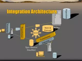
SAVI Program Concepts • Start integrated, stay integrated • Integrate, analyze, then build • Architecture-centric, single truth – Model Repository • Distributed and Heterogeneous – Data Exchange Layer • Standards based • Semantically precise for quantitative analyses • Mixed maturity development – incremental V&V • Support the business case • Collaborate – leverage “Best-In-Class”
As-Is to To-Be Single Truth • Models from multiple de-sign teams contain multiple interdependent properties • Each design team identifies multiple ways of modeling (abstracting) these common properties - multiple models and tools • Each team abstracts properties in different ways • Each team’s approach to modeling common properties may not be equivalent • Results: multiple truths As-Is Distributed Annotated Architectural Reference Model Data Exchange Layer Model Repositories Consistency checks after each mod Consistency checks after each mod To-Be
Multiple Groups/Tools/Repositories Airframer Data Exchange/Translation Supplier 1 Sales Engineering Supplier 2 Manufacturing Customer 1 Service Customer 2 Model Repository Regulator
Late Discovery of Problems 20.5% 110x 80% of accidents due to operator error High recertification cost of design error corrections leads to 75% of operator time spent in work-arounds Requirements Engineering Acceptance Test 80% late error discovery at high repair cost 70% requirements and system interaction errors 0%, 9% 40x 70% 500-1000x System Design System Test 1x 70%, 3.5% 10%, 50.5% 16x Software Architectural Design 20-100x Integration Test System-level fault propagation due to incomplete/inconsistent requirements and mismatched assumptions. Component Software Design 20%, 16% Unit Test 5x Sources: NIST Planning report 02-3, The Economic Impacts of Inadequate Infrastructure for Software Testing, May 2002. D. Galin, Software Quality Assurance: From Theory to Implementation, Pearson/Addison-Wesley (2004) B.W. Boehm, Software Engineering Economics, Prentice Hall (1981) 3-6x Where faults are introduced INCOSE 2010 Where faults are found The estimated nominal cost for fault removal Rework and certification dominates development cost Delivery delays not known until late into project schedule
Development by System Integrator Source Selection RFI Phase Develop / Update System Requirements RFI Response AFE 58 As-Is Acquisition Process • As-Is Process [new/modifiedsubsystems] System Concept Development [system feedback] [feedback] System Conceptual Design Subsystem Acquisition Source Selection RFP Phase Subsystem Conceptual Design Data System-Level System Requirements Review [subsystem feedback] System Preliminary Design [system feedback] System Design Data Subsystem Preliminary Design Description [subsystem feedback] System-Level System Preliminary Design Review System Detailed Design [system feedback] Subsystem Preliminary Design Description System Design Data [subsystem feedback] System-Level Critical Design Review Subsystem Test Article System Design Data System-level Integration Test [subsystem feedback] System Design Data System Production
Development by System Integrator Source Selection RFI Phase Develop / Update SAVI-Compliant System Requirements RFI Response AFE 58 To-Be Acquisition Process • To-Be Process Start Integrated [new/modifiedsubsystems] Model-Based System Concept Development [system feedback] [feedback] Model-Based System Conceptual Design Subsystem Acquisition Source Selection RFP Phase Subsystem Conceptual Design Data System-Level System Requirements Review Stay Integrated [subsystem feedback] Model-Based System Preliminary Design [system feedback] Model-Based System Design Data Subsystem Preliminary Design Description These look like minor changes … but …. SAVI Technology works properly only when the Develop/Update System Requirements, System Concept Development, and System Conceptual Design activities deploy a standardized model based design and requirement development approach. Model-based Systems Engineering Is not a small change. [subsystem feedback] System-Level System Preliminary Design Review System Detailed Design [system feedback] Subsystem Preliminary Design Description Model-Based System Design Data [subsystem feedback] System-Level Critical Design Review Subsystem Test Article Model-Based System Design Data System-level Integration Test [subsystem feedback] Model-BasedSystem Design Data System Production
AFE 58 PoC Models Second Level Abstraction: Tier 2 Flight Guidance SystemAADL Model in Graphic Form Top Level Abstraction: Tier1 A/C Model PowerPoint Representation More detailedAADL representationof a system AADL model hierarchy Multi levels all systems levels, single system level Multi-criteria weight, power, … Analysis based on the same hierarchical description AADL representation Top Level Abstraction: Tier1 A/C Model AADL Model in Graphic Form Third Level Abstraction: Tier 3 Air Data Subsystem
AFE 58 Models Based on AADL • Connection Consistency • AADL is a strongly-typed Architectural Definition Language • Generates code that supports analysis • Allows consistency checking to be implemented
AFE 58 Return on Investment • Estimation flow – software dominates • COCOMO II Results (Multiplier of 1.55 used to include hardware effects)
AFE 58 Road Map • Based on Assumptions Prior to 2008
AFE 58 Assessment • Will AFE 58 sufficiently evaluate the technical risks to know that SAVI is possible? • Yes: we have demonstrated the key concepts and technologies to a level that will reduce technical risk to an acceptable level for the participating member companies. • Will the ROI development reasonably scope the financial commitment and potential return for participating member companies? • The ROI methodology is very conservative - built on accepted precedent and explicit assumptions and validated with multiple sources of data. It will allow participating companies to fine tune the ROI for their own, unique situations. • Is the SAVI program too ambitious for AVSI? • Jury is out: member companies must individually assess the validity of the ROI and the level of technical risk in the context of their own business environments. AFE 58 demonstrates feasibility (it can be done) and points to mutually benefits with the right level of resource commitment. The upside potential benefits are very enticing, but it requires considerable investment to reap the benefits. We will need to be innovative in structuring the path forward to make this palatable to participants.
Revised Road Map • Incremental Development Emphasized
AFE 59 Use Case Demonstrations • “Fit” Demonstration • Electronic Case Element • Reliability Demonstration • MTBF Model • Interface with Moebis • Safety Demonstration • FHA • FMECA • Behavior Demonstration • Aeroelastic (FEM) Model of Lifting Surface • Hydromechanical Model of Control Elements
AFE 59 Return on Investment • Still Using COCOMO II with SCAT Added • RoI Estimates Still Very High • Small Deviation in Results from Monte Carlo Runs • Sensitivity to Assumed Error Discovery Using SAVI Assumes 66% of software defects are discovered and corrected during the SAVI VIP • Even at 10% discovery/correction of software errors, the RoI lower bound (for a triangular distribution) is ~+4%/year
AFE 59S1 Return on Investment • Compared Estimates with SEER Results • SEER Model Shows Similar RoI
Aircraft Monitoring System • AADL Model Structure • Interface uses AADL features structure features Signals: requiresbusaccess SignalFlow; Mountings: requiresbusaccess MountPoints; HydraulicPower: requiresbusaccess HydraulicFlow; ElectricPower: requiresbusaccess ElectricPowerFlow; -- Interfaces for other subsystems - added per 3/29/12 minutes FCS_DMS: portgroup FCStoDMS; FCS_CDS: portgroup FCStoCDS;
CH-47 CAAS Upgrade (AMRDEC) • CAAS – “fully integrated flight and mission management capability…” • Common digital architecture for U. S. Army rotary wing aircraft • Fully open, non-proprietary system embracing commercial standards • Consistent, intuitive user interface for displays that allows control of all avionics subsystems
SAVI Proof of Concept Takeaways • No Roadblocks • Architecture-centric Analysis Works • Model-based Elements Feasible • Narrative elements were captured • Property exchanges were carried out • Inconsistencies were detected and quantified • Cyber-Physical Interfaces Were Demonstrated with AADL Model • MATLAB/Simulink, LISA (FEM) – simple scripts (need to be automated and verified) • Simple fit geometries (CATIA) • Safety and Reliability tools for FHA and FMECA; MTBF analysis • Major Lessons – Focus for SAVI Version 1.0 • “Single Truth” Does not Imply Single Language • AADL’s strong semantics facilitates architectural analyses • SysML graphical tools are helpful for data flow and to illustrate Use Cases • Two-way translations are available (Cofer’s work for DARPA – extended for SAVI) • Other translations will be needed • Repository Interfaces Are Complex • Must facilitate consistency checking • Must provide protection for intellectual property • Must provide automated configuration management • Must provide verification path • Must underpin and encourage formal analysis • Must spell out needed translators/converters for unique project requirements • Involve Tool Vendors and Standards Body (ies)
Focus of SAVI V. 1.0B Focus of SAVI V. 1.0A SAVI Roadmap for Next Stage Focus of SAVI V. 1.0C Focus of SAVI V. 1.0D
Aircraft Braking System Safety • Work flow
SAVI Version 1.0 Actions • SAVI Initial Capability Phase (Version 1.0A) • Specify the SAVI Virtual Integration Process • Use AADL Requirements Annex • Requirements Generation • Requirements Validation • Requirements Traceability • Spell Out Multiple Language Interfaces • Define needed translators/mapping tools • Evaluate mapping and translators available • Document the VIP (set initial baseline) • Specify Model Bus and Data Exchange Layer • Initiate Application of the VIP Process • Apply Analysis Techniques Used in SAVI • Illustrate Specification with Models • Implement translators • Description of Repository Interfaces • Capture Functionality of System • Encapsulate Consistency Checking • Set up Version Management Scheme • Illustrate Specification with Models • Implement translators • Involve Tool Vendors • Capture Inputs to Version 1.0 Specification • Encourage setting roadmaps for tool development
Conclusion • The problems caused by escalating complexity are being felt the majority of large aerospace systems developments. Thus the need is immediate to develop the next generation of system design tools and processes. • The SAVI Program is a collaborative, industry-led project developing the processes and technologies necessary to enable virtual integration of complex systems. • The problem space is large and diverse. An industry-consensus effort leading to a set of implementable standards is necessary for a viable solution. • The impact will be on the full product lifecycle. All stakeholders in the design, development, manufacture, distribution, operation, and maintenance of complex systems need to be engaged. • A solution will require continued investment and direction from both government and industry and employ technology development with academic partners.
Questions? Contacts: Dr. Don Ward Phone: (254) 842-5021 Mobile: (903) 818-3381 dward@avsi.aero Dr. Dave Redman Office: (979) 862-2316 Mobile: (979) 218-2272 dredman@avsi.aero