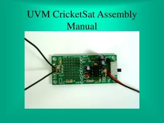

CricketSat Construction
E N D
Presentation Transcript
Parts List CricketSat Assembly
Altium CricketSat Assembly
Schematic CricketSat Assembly
Follow the GUIDE Now, Use your CricketSat construction guide to build your CricketSat Pay close attention to the components that MUST go in correctly – 8 pin socket and LED CricketSat Assembly
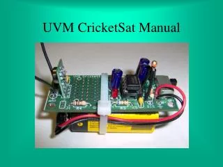
Follow the GUIDE Its easy to confuse the Thermistor with the ceramic capacitors. The Thermistor is darker orange/red and has longer legs. CricketSat Assembly
Tips for the thermistor The thermistor (R2) is connected here. CricketSat Assembly
Trouble Shooting Check all solder joints to make sure that all have complete coverage of the via. Make sure there are no bridges (overlapping) solder between connections. CricketSat Assembly
Once you’ve successfully completed the build of your CricketSat – take lots of selfies with your CricketSat and post!! CricketSat Assembly
1. Tum the switch on in this position. 2. If the LED lights up, go to the next page. Off On .3 If the LED does not lights up, you got big troubles, but we will tell you how to fix it. See page 13 for trouble shooting your CricketSat.
1. Turn multimeter to Hz%. Off On 2. Connect black lead to pin 1 of J2, Connect red lead to pin 2 of Je. 3. You should read between 1,1000 and 1500 HZ. If you do, you are now ready to calibrate your CricketSat – another document. 4. IF you read zero Hz, then go to page 13 to trouble shoot your CricketSat.
Trouble Shooting your CricketSat 1. Turn off the switch. Remove he LM555 from the socket. 3. You must to re-inspect the bottom of you PCB to make sure you have good solder joints on everything and not bridges. If you find problems and fix them go back to page 10. 2. REMOVE the battery. Off On 4. You will now use your multimeter to check to make sure the circuit has the proper continuity. See page 14. 5. In all your trouble shooting, keep notes on all of the measurements you make.
Trouble Shooting your CricketSat Checking continuity 4. You will now use your multimeter to check to make sure the circuit has the proper continuity. See page 14. 3. Turn the meter switch to the diode/buzzer position. Short the read an black leads together and press the diode/busser button until you hear the buzzer. 1. Be sure your CricketSat is turned off. Remove the LM555 from the socket. 2. REMOVE the battery. Off On
Trouble Shooting your CricketSat Checking continuity 2. These pins are connected together on the PCB (see schematic circled) and thus shorted or have continuity between them. 1. Put the multimeter lead in the socket pins 4 and 8. See pin labeling below, right. Buzzer should sound. 3. If you do not get continuity, then check the PCB to determine what is wrong. • 4. Continue checking other pins: • 2-6 • Ground on PCB to other pins: • To J2 pin 1 • To J1 pin 1 Off On 8 7 6 5 1 2 3 4
Trouble Shooting your CricketSat Checking Resistance 4. You will now use your multimeter to check to make sure the circuit has the proper continuity. See page 14. 3. Turn the meter switch to the resistance - ohms position. Short the read an black leads together and press the range button until you read zero. 1. Be sure your CricketSat is turned off. Remove the LM555 from the socket. 2. Make sure the battery is removed. Off On
Trouble Shooting your CricketSat Checking Resistance and Capacitance 1. Put the multimeter lead in the socket pins 7 and 8. You should get what? Look at the schematic – 2.7k ohms. 2. Next check between 7 and 6. You will be reading the thermistor ~ 10k ohms at room temperature. • 3. Continue checking other pins: • 3 to pin J2 pin 2 – 330 ohms • You can not check resistance across a capacitor or a diode with the resistance setting on the multimeter. Use the capacitance setting on the meter to check capacitance. Off On 8 7 6 5 1 2 3 4 4. If you find errors, maybe a bad component or wrong component.
Trouble Shooting your CricketSat Checking Voltages 1. Put the battery back in and turn the switch on. 2. Turn the meter to Vdc and check between pins 1 and 8 on the LM555 socket. You should get approx. minus 9v. Minus because the red lead is on the ground connection. If voltage is below 9v, change batteries. 3. Look at the schematic and determine other places where you should also get 9v. If no voltage, trouble shoot. What is cause? Off On 4. If you find errors, maybe a bad components. wrong components or bad connections.