Logic Design Essentials: Flip-Flops, Latches, Registers, Counters, and FSMs
Discover the fundamentals of flip-flops, latches, registers, counters, and Finite State Machines (FSMs). Learn how memory storage elements function, study state diagrams, and delve into the design and operation of these crucial components in computer architecture.

Logic Design Essentials: Flip-Flops, Latches, Registers, Counters, and FSMs
E N D
Presentation Transcript
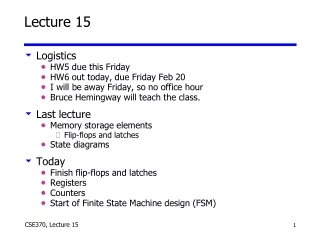
Lecture 15 • Logistics • HW5 due this Friday • HW6 out today, due Friday Feb 20 • I will be away Friday, so no office hour • Bruce Hemingway will teach the class. • Last lecture • Memory storage elements • Flip-flops and latches • State diagrams • Today • Finish flip-flops and latches • Registers • Counters • Start of Finite State Machine design (FSM)
The “WHY” slide • Registers and Counters • Registers and counters are very simple yet powerful examples of how you can use the basic memory elements to conduct productive behavior. They are used everywhere in a computer.
How do we make a D flip flop? W X Q Clk Q’ Y Z D Falling edge-triggered flip-flop If Clk=1 then X=Y=0 and SR-latch block holds previous values of Q,Q’ also Z=D’ and W=Z’=D When Clk0 then Y (set for SR-latch block) becomes Z’=D and X (reset for SR-latch block) becomes W’=D’ so Q becomes D This is stable until D or the Clk switches While Clk=0, if D switches then Z becomes 0 and X and W hold their previous values and Y=X’=D as before.
Terminology & notation Rising-edge triggered D flip-flop Output Input Output D D Q Q Q Q CLK CLK Positive D latch Output Input D Q Output Q CLK Falling-edge triggered D flip-flop Negative D latch Output Output Input Input D Q Output Output Q CLK
Latches versus flip-flops D Q Q D Q Q CLK CLK D Qff Qlatch CLK behavior is the same unless input changes while the clock is high
The master-slave D Master D latch Slave D latch Output Input D Q D Q CLK master-slave D flip-flop
Master-Slave D implements D flip-flop D Q Q D Q Q CLK CLK D Qff Qlatch’ Qmasterslave CLK
T flip-flop Full name: Toggle flip-flop Output toggles when input is asserted If T=1, then Q Q' when CLK If T=0, then Q Q when CLK Input(t) Q(t) Q(t + t) Input Q T Q 0 0 0 > 0 1 1 1 0 1 CLK 1 1 0
Clear and preset in flip-flops Clear and Preset set flip-flop to a known state Used at startup, reset Clear or Reset to a logic 0 Synchronous: Q=0 when next clock edge arrives Asynchronous: Q=0 when reset is asserted Doesn't wait for clock Quick but dangerous Preset or Set the state to logic 1 Synchronous: Q=1 when next clock edge arrives Asynchronous: Q=1 when reset is asserted Doesn't wait for clock Quick but dangerous R S D Q
Registers • Group of storage elements read/written as a unit. • Store related values (e.g. a binary word) • Collection of flip-flops with common control • Share clock, reset, set lines • Example: • Storage registers • Shift registers • Counters
R S D Q Storage registers • Basic storage registers use flip flops • Example: 4 bit storage register OUT1 OUT2 OUT3 OUT4 "0" R S R S R S D Q D Q D Q CLK IN1 IN2 IN3 IN4
OUT1 OUT2 OUT3 OUT4 D Q D Q D Q D Q IN CLK Shift registers • Hold successively sampled input values • Delays values in time • Example: 4-bit shift register • Stores 4 input values in sequence
serial transmission parallel outputs CLK CLK parallel inputs OUT D Q D Q D Q D Q IN CLK Shift-register applications • Parallel-to-serial conversion for signal transmission • Pattern recognition (circuit recognizes 1001)
OUT1 OUT2 OUT3 OUT4 D Q D Q D Q D Q IN CLK OUT1 OUT2 OUT3 OUT4 D Q D Q D Q D Q IN CLK Counters • Ring counter: Sequence is 1000, 0100, 0010, 0001 • Assuming one of these patterns is the starting state • Johnson counter: Sequence is 1000, 1100, 1110, 1111, 0111, 0011, 0001, 0000
OUT0 OUT1 OUT2 OUT3 D0 D1 D2 D3 D Q D Q D Q D Q CLK "1” A binary counter • Has logic between flip-flops Flip low-order bit each clock cycle Flip next bit when all lower order bits are 1 Flip next bit when both lower order bits are 1 Flip next bit in cycle when low- order bit is 1
“States” for finite state machines are kept in the storage elements • Combinational logic and storage elements • Localized feedback loops • Choice of storage elements alters the logic CombinationalLogic Inputs Outputs State Inputs State Outputs Storage Elements
010 111 001 In = 1 In = 0 In = 0 100 110 In = 1 Finite-state machines (FSMs) • States: Possible storage-element values • Transitions: Changes in state • Clock synchronizes the state changes • Sequential logic • Sequences through a series of states • Based on inputs and present state
OUT1 OUT2 OUT3 D Q D Q D Q IN CLK 1 110 100 0 1 1 1 1 1 010 101 0 111 1 000 0 0 1 0 0 0 001 011 0 Drawing state diagrams • Show input values on transition arcs • Show output values in state nodes
010 011 001 000 100 3-bit up-counter 110 101 111 Counters revisited • Great simple examples of state machines • Output is the counter’s state • Next state is well defined • Does not depend on input (no inputs)
FSM design procedure (using counters) 1. Draw a state diagram 2. Draw a state-transition table 3. Encode the next-state functions • Minimize the logic using k-maps • Implement the design We will use a ‘3-bit up counter’ as an example
010 011 001 000 100 3-bit up-counter 110 101 111 1. Draw a state diagram
2. Draw a state-transition table • Like a truth-table • State encoding is easy for counters Use count value current state next state0 000 001 11 001 010 22 010 011 33 011 100 44 100 101 55 101 110 66 110 111 77 111 000 0
C3 C3 N1 N2 1 1 1 10 0 0 0 0 1 1 01 0 0 1 C1 C1 C2 C2 C3 N3 0 0 1 10 1 0 1 C1 C2 3. Encode the next state functions • Assume D flip-flops as state elements C3 C2 C1 N3 N2 N10 0 0 0 0 10 0 1 0 1 00 1 0 0 1 10 1 1 1 0 01 0 0 1 0 11 0 1 1 1 01 1 0 1 1 11 1 1 0 0 0 N1 := C1' N2 := C1C2' + C1'C2 := C1 xor C2 N3 := C1C2C3' + C1'C3 + C2'C3 := C1C2C3' + (C1' + C2')C3 := (C1C2) xor C3
OUT1 OUT2 OUT3 D Q D Q D Q CLK "1" 4. Implement the design • 3 flip-flops hold state • Counter is synchronously clocked • Minimized logic computes next state