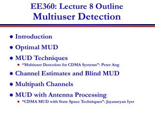
Multiuser Detection in CDMA
Multiuser Detection in CDMA. A. Chockalingam Assistant Professor Indian Institute of Science, Bangalore-12 achockal@ece.iisc.ernet.in http://ece.iisc.ernet.in/~achockal. Outline. Near-Far Effect in CDMA CDMA System Model Conventional MF Detector Optimum Multiuser Detector

Multiuser Detection in CDMA
E N D
Presentation Transcript
Multiuser Detection in CDMA A. Chockalingam Assistant Professor Indian Institute of Science, Bangalore-12 achockal@ece.iisc.ernet.in http://ece.iisc.ernet.in/~achockal
Outline • Near-Far Effect in CDMA • CDMA System Model • Conventional MF Detector • Optimum Multiuser Detector • Sub-optimum Multiuser Detectors • Linear Detectors • MMSE, Decorrelator • Nonlinear Detectors • Subtractive Interference cancellers (SIC, PIC) • Decision Feedback Detectors Dept of ECE, IISc, Bangalore
DS-CDMA • Efficient means of sharing a given RF spectrum by different users • User data is spread by a PN code before transmission • Base station Rx distinguishes different users based on different PN codes assigned to them • All CDMA users simultaneously can occupy the entire spectrum • So system is Interference limited Dept of ECE, IISc, Bangalore
DS-SS • DS-SS signal is obtained by multiplying the information bits with a wideband PN signal Information Bits Carrier Modulation Tb PN Signal Information Bits t Tb =NTc Tc N : Processing Gain PN Signal t Dept of ECE, IISc, Bangalore
Processing Gain • Ratio of RF BW (W) to information rate (R) (e.g., In IS-95A, W = 1.25 MHz, R = 9.6 Kbps i.e., ) • System Capacity (K) proportional to (voice activity gain) (sectorization gain) (other cell interference loss) (typically required) Dept of ECE, IISc, Bangalore
Near-Far Effect in DS-CDMA • Assume users in the system. • Let be the average Rx power of each signal. • Model interference from users as AWGN. • SNR at the desired user is • Let one user is near to BS establishes a stronger Rx signal equal to • SNR then becomes • When is large, SNR degrades drastically. • To maintain same SNR, has to be reduced • i.e., loss in capacity. Dept of ECE, IISc, Bangalore
Near-Far Effect • Factors causing near-far effect (unequal Rx Signal powers from different users) in cellular CDMA • Distance loss • Shadow loss • Multipath fading (Most detrimental. Dynamic range of fade power variations: about 60 dB) • Two common approaches to combat near-far effect • Transmit Power Control • Near-far Resistant Multiuser Detectors Dept of ECE, IISc, Bangalore
CDMA System Model Data of User 1 Chip shaping filter Spreading Sequence of user 1 AWGN Data of User 1 Chip shaping filter To Demod/ Detector Spreading Sequence of user 2 Data of User 1 Chip shaping filter Spreading Sequence of user K Dept of ECE, IISc, Bangalore
Matched Filter Detector (MFD) MF User 1 MF User 2 MF User K Correlation Matrix Dept of ECE, IISc, Bangalore
MFD Performance: Near-Far Scenario 2-User system: 0.4 NFR = 20 dB 0.1 NFR = 10 dB Bit Error Rate NFR = 5 dB NFR = 0 dB E/b/No (dB) • Problem with MF Detector: Treats other user interference • (MAI) as merely noise • But MAI has a structure which can be exploited in the • detection process Dept of ECE, IISc, Bangalore
Optimum Multiuser Detector • Jointly detect all users data bits • Optimum Multiuser Detector • Maximum Likelihood Sequence Detector • Selects the mostly likely sequences of data bits given the observations • Needs knowledge of side information such as • received powers of all users • relative delays of all users • spreading sequences of all users Dept of ECE, IISc, Bangalore
Optimum Multiuser Detector • Optimum ML detector computes the likelihood fn and selects the sequence that minimizes • The above function can be expressed in the form where and is the correlation matrix with elements where Dept of ECE, IISc, Bangalore
Optimum Multiuser Detector • results in choices of the bits of the users • Thus Optimum Multiuser Detector is highly complex • complexity grows exponentially with number of users • Impractical even for moderate number of users • Need to know the received signal energies of all the users Dept of ECE, IISc, Bangalore
Suboptimum Detectors • Prefer • Better near-far resistance than Matched Filter Detector • Lesser complexity (linear complexity) than Optimum Detector • Linear suboptimum detectors • Decorrelating detector • MMSE detector Dept of ECE, IISc, Bangalore
Decorrelating Detector Linear Transformation and Detector Decision For the case of 2 users and Dept of ECE, IISc, Bangalore
Decorrelating Detector • For the case of 2 users and • operation has completely eliminated MAI components at the output (.e., no NF effect) • Noise got enhanced (variance increased by a factor of ) Dept of ECE, IISc, Bangalore
Decorrelating Detector • Alternate representation of Decorrelating detector • By correlating the received signal with the modified signature waveforms, the MAI is tuned out (decorrelated) • Hence the name decorrelating detector Dept of ECE, IISc, Bangalore
MMSE Detector • Choose the linear transformation that minimizes • the mean square error between the MF outputs • and the transmitted data vector Linear Transformation and Detector Decision Dept of ECE, IISc, Bangalore
MMSE Detector • Choose the linear transformation • where is determined so as to minimize the • mean square error (MSE) • Optimum choice of that minimizes is Dept of ECE, IISc, Bangalore
MMSE Detector Linear Transformation and Detector Decision • When is small compared to the diagonal • elements of MMSE performance approaches • Decorrelating detector performance • When is large becomes (i.e., AWGN • becomes dominant) Dept of ECE, IISc, Bangalore
Adaptive MMSE • Several adaptation algorithms • LMS • RLS • Blind techniques Estimate of the data bits Linear Transversal Filter Re() Training bits Adaptive Algorithm Dept of ECE, IISc, Bangalore
Performance Measures • Bit Error Rate • Asymptotic efficiency: Ratio of SNRs with and without interference represents loss due to multiuser interference • Asymptotic efficiency easy to compute than BER Dept of ECE, IISc, Bangalore
Performance Measures Optimum Detector DC 1.0 MMSE MF Detector 0.0 -20.0 -10.0 0.0 10.0 20.0 Dept of ECE, IISc, Bangalore
Subtractive Interference Cancellation • Multistage interference Cancellation approaches • Serial (or successive) Interference Canceller (SIC) • sequentially recovers users (recover one user per stage) • data estimate in each stage is used to regenerate the interfering signal which is then subtracted from the original received signal • Detects and removes the strongest user first • Parallel Interference Canceller (PIC) • Similar to SIC except that cancellations are done in parallel Dept of ECE, IISc, Bangalore
SIC MF Detector MF Detector Matched Filter Remodulate & Cancel Remodulate & Cancel Stage-1 Stage-m Dept of ECE, IISc, Bangalore
m-th Stage in SIC MF Detector MF User m Select Strongest User MF User K Remodulate & Cancel Dept of ECE, IISc, Bangalore
Performance of SIC • Good near-far resistance • Most performance gain in achieved using just 2 to 3 stages • High NFR can result in good performance! • Provided accurate estimates of amptitude and timing are available • Sensitive to amplitude and timing estimation errors • increased loss in performance for amplitude estimation errors > 20 % • Some amount of power control may be required to compensate for the near-far resistance loss due to imperfect estimates and low NFR Dept of ECE, IISc, Bangalore
PIC MF User 1 MF User K Stage 1 Stage j Dept of ECE, IISc, Bangalore
Performance of PICPerformance of PIC • Good near-far resistance • Similar performance observations as in SIC • Performance of PIC depends more heavily on the relative amplitude levels than on the cross-correlations of the user spreading codes • Hybrid SIC/PIC architectures Dept of ECE, IISc, Bangalore
DFE Detector MF User 1 FFF Centralized Decision Feedback MF User K FFF • Feedback current data decisions of the stronger users as well • DFE multiuser detectors outperform linear adaptive receivers • Complexity, error propagation issues Dept of ECE, IISc, Bangalore