Download
1 / 30
310 likes | 425 Vues
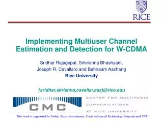
Implementing Multiuser Channel Estimation and Detection for W-CDMA. Sridhar Rajagopal, Srikrishna Bhashyam, Joseph R. Cavallaro and Behnaam Aazhang Rice University {sridhar,skrishna,cavallar,aaz}@rice.edu.

E N D
Implementing Multiuser Channel Estimation and Detection for W-CDMA Sridhar Rajagopal, Srikrishna Bhashyam, Joseph R. Cavallaro and Behnaam Aazhang Rice University {sridhar,skrishna,cavallar,aaz}@rice.edu This work is supported by Nokia, Texas Instruments, Texas Advanced Technology Program and NSF
Organization • Joint Estimation & Detection • An Implementation-Friendly Scheme • Simulations • Architectural Features • Task Partitioning • Area-Time Tradeoffs • Conclusions • Future Work
Base-station Receiver Antenna Data Multiuser Detection Decoder Detected Bits Delay Decision Feedback Multiple Users + Demod -ulator Channel Estimation d MU X MU X Pilot b Base-Station with MUD
Joint Estimation & Detection • Jointly estimate the channel response and detect all the user’s bits. • Shown to have better performance as well as reduced computational complexity. • Maximum Likelihood Based Channel Estimation • [C.Sengupta et al. : PIMRC’1998 WCNC’1999] • Differencing Multistage Detection based on Parallel Interference Cancellation • [G.Xu et al. : SPIE’1999]
time bi-1 bi ri Computations Involved delay • Model • Compute Correlation Matrices Bits of K async. users aligned at times I and I-1 Received bits of spreading length N for K users
Multishot Detection Solve for the channel estimate, Ai Multishot Detection
Differencing Multistage Detection • Stage 0 [ Matched Filter Detector] • Stage 1 [ to build differencing vector] • Successive Stages S=diag(AHA) y - soft decision d - detected bits (hard decision)
Structure of AHA Not difficult to Compute AHA Block Bi-Diagonal Matrix : Use Structure
Drawbacks • Matrix Inversion/ Decomposition Needed • Result not available till end of computation • Delay before Detection • Difficult for Tracking • Higher Precision Needed • Floating Point Units • Larger Memory Requirements • Storage of elements to compute inverse • Float = 32 bits / Input accuracy = 12-14 bits • SLOW! - Difficult to meet Real-Time • [S.Rajagopal et al. : TI DSPFest’1999]
Proposed Base-Station No Multiuser Detection TI's Wireless Basestation (http://www.ti.com/sc/docs/psheets/diagrams/basestat.htm)
New Scheme • Iterative Method to find the Channel Estimates • [S.Bhashyam et al. : WCNC’2000 (submitted)] • Can be easily adapted to Tracking for Fading Channels • Fixed Point Implementation • Estimates ready for detection Immediately • Simpler Hardware and Software. • Computation Savings only Per Bit
Iterative Scheme • Tracking • Slow Fading : Large Window L • Fast Fading : Smaller Window L • Method of Steepest Descent • Stable convergence behavior • μ fixed : Bit-by-Bit update • Matches Closely to the Scheme with Inversions
Comparison of BER using Channel Estimates by inversion and by iteration -1 10 -2 10 BER MF ActMF ML ActML -3 10 4 5 6 7 8 9 10 11 12 SNR Simulations - AGWN Channel Detection Window = 12 SINR = 0 Paths =3 Preamble =150 10000 bits/user MF – Matched Filter ML- Maximum Likelihood ACT – using inversion
0 10 MF - Static MF - Tracking ML - Static ML - Tracking -1 10 BER -2 10 -3 10 4 5 6 7 8 9 10 11 12 SNR Fading Channel with Tracking Doppler = 10 Hz, 1000 Bits,15 users, 3 Paths
DSP Implementation • C6201 Texas Instruments • Fixed Point Processor • 200 MHz • 32 -bit VLIW Architecture • 8 Functional Units • 2 Multipliers • 4 Adders • 2 Load/Store • TI C Compiler
Simulation • Work in Progress! • Why better? • Fixed Point Implementation - Faster on DSPs • Higher Clock Speeds / Faster Multiplications • More SIMD Parallelism due to smaller wordlength. • Software Code Simpler to write • Smaller Program Size • Problems • Input Bit Precision Analysis • Overflows
Base-station Receiver Antenna Data Multiuser Detection Decoder Detected Bits Delay Decision Feedback Multiple Users + Demod -ulator Channel Estimation d MU X MU X Pilot b Task - Partitioning the Algorithm
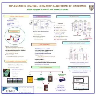
Task Decomposition S.Das et al : Asilomar’99 Block I Block III Block II Task B Correlation Matrices (Per Bit) Iterate Matrix Products Block IV M UX d A0HA1 O(K2N) Multistage Detection (Per Window) A[R] O(K2N) Rbr[R] O(KN) b A0HA0 O(K2N) Rbr[I] O(KN) M UX Data’ A[I] O(K2N) d O(DK2M) Rbb O(K2) A1HA1 O(K2N) Pilot AHr O(KND) Data Multistage Detection Channel Estimation TIME Task A
Channel Estimation Architecture • Detection Architecture • One version already ready • [G.Xu - Master’s Thesis 1999] • Advantages over DSP Implementation: • Optimal Memory Utilization • Custom Blocks for exploiting available pipelining and parallelism • Parts could be mapped to FPGA / Reconfigurable logic • Shows theoretical bounds for maximum achievable Data Rates • Shows how tasks could be split among different processors
Window b0b0’ (2K2) Inverter (2 K2) A [R] (KN) b0 (2K) b Rbb (2 K2) Multiplier (2 K2N) MUX (2 K2) bb’ (2 K2) Inverter (2K) MUX (2K) Rbr [R] (KN) r[R] r0 (N) Atmp [R] >> (4 K2) MUX (N) A [I] (KN) Multiplier (2 K2N) Inverter (2K) MUX (2K) Rbr [I] (KN) r[I] r0 (N) Atmp >> (4 K2) MUX (N) Block Diagram Each block shows no. of “operations” in it. REAL bit IMAG 8-bit
bit 8-bit Channel Estimation Each block shows no. of “operations” in it. Window b0b0’ (2K2) Inverter (2 K2) A [R] (KN) b0 (2K) b Rbb (2 K2) Multiplier (2 K2N) REAL MUX (2 K2) bb’ (2 K2) Inverter (2K) MUX (2K) Rbr [R] (KN) r[R] r0 (N) Atmp [R] >> (4 K2) MUX (N)
b0b0’ (2K2) Inverter (2 K2) MUX (2 K2) bb’ (2 K2) Auto-correlation Structure • b,b0 are 1-bit • Subtraction by using inverter • Rbb using a Counter • Fully Parallel • 2K2 elementsO(1) Time • Pipelined [with LOAD] • 2K elements O(K) Time • Serial [with LOAD] • 1 element O(2K2) Time Rbb (2 K2)
Inverter (2K) MUX (2K) Rbr [R] (KN) MUX (N) Cross-Correlation Structure • r is 8-bit, b is 1-bit • Rbr using 8-bit Adders • Based on sign of b • Fully Parallel KN, O(1) • Pipelined N , O(K) • Serial 1, O(KN)
A [R] (KN) Rbb (2 K2) Multiplier (2 K2N) REAL Rbr [R] (KN) Atmp [R] >> (4 K2) Iterative Update Structure • 8-bit Multipliers • 16-bit Adders for Multiplier • 8-bit Adders for A • Parallel KN, O(K) • Pipelined N , O(K2) • Serial 1, O(K2N)
Elements in each block Example : N = 32,L =100, K =32 Fully Parallel Solution : 4K Multipliers, 12K Adders : O(32) Time Pipelined Solution :100 Multipliers, 300 Adders : O(1K) Time
Conclusions • Iterative Scheme for Joint Estimation & Detection • No loss in algorithm performance • Suitable for Hardware Implementation • On DSPs, FPGAs and ASICs • Supports Tracking for Fading Channels • Fixed Point Implementation Feasible • ASIC architecture • To exploit available pipelining and parallelism • Multiuser Channel Estimation and Detection algorithms POSSIBLE to IMPLEMENT for W-CDMA.
Future Work • MS • Extend Architecture to Long Codes • Task Partition the algorithm on the Sundance Multi-DSP/FPGA board to achieve real-time • Post-MS • Downlink • Architectures to Min. Power Consumption /Area • Implementing Coding/Decoding Blocks and integrate • RENE’
5 x 10 Data Rates for Different Levels of Pipelining and Parallelism 3 2.5 (Parallel A) (Parallel+Pipe B) (Parallel A) (Pipe B) (Parallel A) B 2 A B Sequential A + B Data Rates 1.5 Data Rate Requirement = 128 Kbps 1 0.5 0 9 10 11 12 13 14 15 Number of Users Data Rates Achieved Assuming Channel Estimation Real-Time
Fading Channel • SNR = 10 dB, Doppler = 10 Hz, 1000 Bits