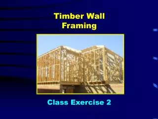
TIMBER FRAMING USING AS 1684.2 SPAN TABLES
TIMBER FRAMING USING AS 1684.2 SPAN TABLES. AS 1684 Teaching Guide. AS 1684-2010 Residential timber-framed construction. AS 1684-2010 Residential timber-framed construction.

TIMBER FRAMING USING AS 1684.2 SPAN TABLES
E N D
Presentation Transcript
TIMBER FRAMINGUSING AS 1684.2 SPAN TABLES AS 1684 Teaching Guide
AS 1684-2010 Residential timber-framed construction AS 1684-2010 Residential timber-framed construction • Go to www.education.WoodSolutions.com.au for up to date teaching resources including an annotated copy of the standard. • This powerpoint presentation is part of a series that has been revised to reflect the requirements of AS 1684 Parts 2 & 3 – 2010 Edition. • Some major changes to this edition include amendments to wall nogging requirements, inclusion of ring beam systems and an Appendix of building practices for engineered wood products (EWPs). • The MGP span tables provided with the Standard have also been amended.
the timber framing standard AS 1684 RESIDENTIAL TIMBER-FRAMED CONSTRUCTION Currently you should be using the 2010 Edition.
AS 1684 TIMBER-FRAMING STANDARD Provides the building industry with procedures that can be used to determine building practice to design or check Construction details, determine member sizes and bracing and fixing requirements for timber framed construction in Non-Cyclonic areas (N1 – N4).
AS 1684.2 – CD Span Tables AS 1684 TIMBER-FRAMING STANDARD Contains a CD of Span Tables (45 sets in all) for wind zones N1 - N4 for the following timber stress grades: Unseasoned Softwood: F5, F7 Seasoned Softwood: F5, F7, F8 MGP10, MGP12, MGP15 Unseasoned Hardwood: F8, F11, F14, F17 Seasoned Hardwood: F14, F17, F27
AS 1684 TIMBER-FRAMING STANDARD Each set of Span Tables contains 53 separate design tables
AS 1684 TIMBER-FRAMING STANDARD Using AS 1684 you should be able to design or check virtually every member in a building constructed using timber framing.
AS 1684 TIMBER-FRAMED CONSTRUCTION Ridge beam Battens Rafters Hanging beams Ceiling battens Ceiling First floor wall frames Roofing External cladding Floor joists Ceiling battens Flooring Lintel Wall frame Wall stud Internal cladding Floor joists Flooring Bearers Stumps or piles
WHERE CAN AS1684 BE USED? AS 1684 Scope and Limitations
Plan: Rectangular, square or “L”-shaped Storeys: Single and two storey construction Pitch: 35o max. roof pitch Width: 16m max. (between the “pitching points” of the roof, i.e. excluding eaves) ax m W m 0 . 6 1 . x a m m W 0 . 6 1 W 16.0 m max. AS 1684 Physical Limitations -
AS 1684 Physical Limitations - Width Width The geometric limits of the span tables often will limit these widths.
Wall Height AS 1684 Physical Limitations – Wall Height The maximum wall height shall be 3000 mm (floor to ceiling) as measured at common external walls (i.e. not gable or skillion ends).
Design Forces on Buildings Suction (uplift) Construction loads (people, materials) DEAD LOAD (structure) Internal pressure Wind LIVE LOADS (people, furniture etc.) Suction DEAD LOAD (structure) AS 1684 Physical Limitations – Design Forces on Buildings AS1684 can be used to design for Gravity Loads (dead & live) and wind loads. (a) Gravity loads(b) Wind loads
Wind Classification AS 1684 Wind Classification Non-Cyclonic Regions A & B only N1 - W28N 100km/h gust N2 - W33N 120km/h gust N3 - W41N 150km/h gust N4 - W50N 180km/h gust
Wind Classification AS 1684 Wind Classification Wind Classification is dependent on : • Building height • Geographic (or wind) region (A for Victoria) • Terrain category (roughness of terrain) • Shielding classification (effect of surrounding objects) • Topographic classification (effect of hills, ridges, etc.)
AS 1684 Wind Classification – Simple References
AS 1684 Using Span Tables Design fundamentals & basic terminology Roof framing Wall framing Floor framing (Click on arrow to move to section required)
AS 1684 Using Span Tables DESIGN FUNDAMENTALS & BASIC TERMINOLOGY
AS 1684 SPAN TABLES Design Fundamentals – Load Path Design Fundamentals You build from the Bottom up. But you design from the Roof down because loads from above can impact on members below. So start with the roof and work down to the ground level.
Roof Load Indirect Load path due to cantilever Ground level AS 1684 SPAN TABLES Design Fundamentals – Load Path Understanding the concept of a ‘load path’ is critical. Loads need to be supported down the building to the ground.
Roof Load Indirect Load path due to cantilever Ground level AS 1684 SPAN TABLES Design Fundamentals – Load Path As a general rule it is necessary to increase the timber member size when: • Load increases (a function of dead, live, wind loads). • Span increases (a function of load paths across openings). • Indirect load paths occur (e.g. cantilevers and offsets). It is possible to decrease timber member size when: • Sharing loads across many members. • Using members with higher stress grades.
MEMBER X A B AS 1684 SPAN TABLES Design Fundamentals – Load Distribution Loads distributed Loads are distributed equally between Points of Support. Of the total load on Member X one half (2000 mm) will be supported by the beam or wall at “A” and the other half (2000 mm) will be supported by the beam or wall at “B”.
MEMBER X AS 1684 SPAN TABLES Design Fundamentals – Load Distribution If Member X is supported at three or more points it is assumed that half the load carried by the spans either side of supports will be distributed equally. A C A B B C Beam A will carry 1000 mm of load Beam B will carry 3000 mm (1000 mm plus 2000 mm on other side) Beam C will carry 2000 mm
AS 1684 SPAN TABLES Terminology – Span Terminology - Span and Spacing Span is the “face-to-face” distance between points capable of giving full support to structural members or assemblies. Joist Span (between internal faces of these support members). Bearers and Floor Joists
AS 1684 SPAN TABLES Terminology – Single Span The span of a member supported at or near both ends with no immediate supports. This includes the case where members are partially cut through over intermediate supports to remove spring.
AS 1684 SPAN TABLES Terminology – Continuous Span The term applied to members supported at or near both ends and at one or more intermediate points such that no span is greater than twice another. NOTE: The design span is the average span unless one span is more than 10% longer than another in which case the design span is the longest span.
AS 1684 SPAN TABLES Continuous Span Example Example: Continuous Span 6000 mm 1/3 1/3 1/3 (2000 mm) (2000 mm) (2000 mm) The center support must be wholly within the middle third. • Span 1 (2000 mm) Span 2 (3925 mm) 75 mm 75 mm 75 mm Span 2 is not to be greater than twice Span 1. This span is used to determine the size using the Continuous Span tables.
AS 1684 SPAN TABLES Terminology - Rafter Span and Overhang Terminology – Rafter Span and Overhang Rafter spans are measured as the distance between points of support along the length of the rafter and NOT as the horizontal projection of this distance. Rafter
AS 1684 SPAN TABLES Design Fundamentals – Spacing Terminology - Span and Spacing Spacing is the centre-to-centre distance between structural members unless indicated otherwise. Joist Spacing (Centreline-to-Centreline) Bearers and Floor joists Bearer Spacing (Centreline-to-Centreline).
AS 1684 SPAN TABLES Terminology – Wall Construction Terminology – Wall Construction Loadbearing wall A wall that supports roof loads, floor loads or both. Non-Loadbearing internal wall A wall that does not support roof or floor loads but may support ceiling loads and act as a bracing wall. The main consideration for a non-loadbearing internal wall is its stiffness (i.e. resistance to movement from someone leaning on the wall, doors slamming shut etc.).
AS 1684 SPAN TABLES Terminology – Roof Construction Terminology – Roof Construction Coupled Roof - rafters are tied together by ceiling joists so that they cannot spread.
AS 1684 SPAN TABLES Terminology – Roof Construction Non-coupled roof - a pitched roof that is not a coupled roof. It includes cathedral roofs and roofs constructed using ridge and intermediate beams Such roofs rely on ridge and intermediate beams to support the centre of the roof. These ridge and intermediate beams are supported by walls and/or posts at either end.
AS 1684 SPAN TABLES Using Span Tables ROOF FRAMING
The “footprint” of a building generally consists of a rectangular block or multiple blocks joined together. Roof shapes are made to cover the footprint while also providing sloping planes able to shed water. AS 1684 SPAN TABLES Roof Framing – Typical Basic Roof Shapes Hip Gable (Cathedral or flat ceiling) Skillion Hip and valley Dutch Hip (or Dutch Gable)
AS 1684 SPAN TABLES Roof Framing – Typical Members
3. Rafters – take batten loads and transfers them to the support structure below e.g. walls. AS 1684 SPAN TABLES Roof Framing - Transferring loads to Pitched Roof 1. Roofing material - takes live/dead/wind loads and transfers them to the Battens. 2. Battens - takes roofing loads and transfers them to the Rafters/Trusses. Support wall
Typical Process Step 1: Determine the wind classification to factor in wind loads (e.g. assume non-cyclonic winds N1 or N2) Step 2: Determine type of roof (e.g. tiled or sheet.) Step 3: Determine batten spacing – typically 330 mm for tiles, or 450, 600, 900, 1200 mm sheet Step 4: Determine batten span – this will be the supporting rafter spacing. Batten Span Batten Spacing AS 1684 SPAN TABLES Roof Framing – Batten Design
AS 1684 SPAN TABLES Roof Framing – Batten Design Step 5: Look up relevant Batten Span Table (i.e. non-cyclonic winds N1 and N2) in AS1684 Vol. 2. Step 6: Choose a table reflecting preferred stress grade. Step 7: Select column in the table for the previous batten “spacing and span” assumptions.
AS 1684 SPAN TABLES Roof Framing – Batten Size Example Inputs required • Wind Classification = N2 • Timber Stress Grade = F8 • Roof Type = Steel Sheet (20 kg/m2) • Batten Spacing = 900 mm • Batten Span = 900 mm
2006 AS 1684 SPAN TABLES Roof Framing – Batten Size Example Simplify table Wind Classification N2 Roof Type - Steel Sheet (20 kg/m2) Timber Stress Grade F8 A 38 x 75 mm F8 Batten Is adequate Batten Spacing = 900 mm Batten Span = 900 mm
Step 1: Determine the wind classification to factor in wind loads. For this example assume non-cyclonic winds N1 or N2. Step 2: Determine dead/live loads on rafters . For this example assume loads are as for a tiled roof with battens (e.g. 60kgs/m2) Step 3: Determine the rafter span. For the example assume a 2100 mm single rafter span. Step 4: Determine the rafter overhang which creates a cantilever span adding extra load. For the example assume a 500 mm overhang. Step 5: Determine the rafter spacing as this determines how much roof loads are shared between rafters. For the example assume a 600 mm spacing . Ridge beam Rafter span O v e r h a n g Rafter Spacing AS 1684 SPAN TABLES Rafter Design - Cathedral Roof Scenario
Step 6 Look up AS1684 Vol 2 AS 1684 SPAN TABLES Rafter Design - Cathedral Roof Scenario Step 7 Choose table reflecting preferred stress grade Step 8 Determine which column in table to select using the previous “rafter spacing” and “single span” assumptions. Step 9 Go down the column until reaching assumed 2100 mm rafter span and 500 mm overhang Step 10 Check the spans work with assumed roof load of 60kgs/m2 Step 11 Read off rafter size – 90x45mm
AS 1684 SPAN TABLES Rafter Design - Cathedral Roof Scenario Inputs required • Wind Classification = N2 • Stress Grade = F8 • Rafter Spacing = 900 mm • Rafter Span = 2200 mm • Single or Continuous Span = Single • Roof Mass (Sheet or Tile) = Steel Sheet (20 kg/m2)
Determine Rafter Size 2006 At least 2200mm Simplifytable Maximum Rafter or Purlin Span & Overhang (mm) Inputs required • Wind Classification = N2 • Stress Grade = F8 • Single or Continuous Span = Single • Rafter Spacing = 900 mm • Rafter Span = 2200 mm • Roof Mass (Sheet or Tile) = Steel Sheet (20 kg/m2) A 100 x 50mm F8 rafter is adequate
Ceiling Joist Design Design variables Timber Stress Grade Ceiling Joist Spacing Ceiling Joist Span Single or Continuous Span AS 1684 SPAN TABLES Ceiling Joist Design Ridge board Rafter Ceiling Joist
Ceiling Joist Design AS 1684 SPAN TABLES Ceiling Joist Design Example Inputs required • Wind Classification = N2 • Stress Grade = F17 • Overbatten = No • Single or Continuous Span = Single • Joist Spacing = 450 mm • Ceiling Joist Span = 3600 mm
2006 At least 3600mm Ceiling Joist Size Simplifytable Inputs required • Wind Classification = N2 • Stress Grade = F17 • Overbatten = No • Single or Continuous Span = Single • Joist Spacing = 450 mm • Ceiling Joist Span = 3600mm A 120 x 45mm F17 ceiling joist is adequate
AS 1684 Span Tables Other Members And Components - Ridge board Ridge board Some members do not have to be designed using span tables. They are simply called up or calculated based on members framing into them.
AS 1684 Span Tables Roof Member Load Impacts The loads from roof members often impact on the design of members lower down in the structure. This impact can be determined from the following load sharing calculations: • Roof Load Width (RLW). • Ceiling Load Width (CLW). • Roof area supported.
AS 1684 Span Tables Roof Member Load Impacts – Roof Load Width RLW is the width of roof that contributes roof load to a supporting member. It is used as an input to Span Tables for: • Floor bearers. • Wall studs. • Lintels. • Ridge or intermediate beams. • Verandah beams. Roof Load Widthsare measured on the rake of the roof.