Download
1 / 37
370 likes | 554 Vues
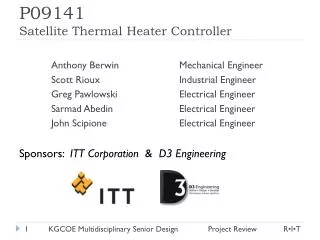
P09141 Satellite Thermal Heater Controller. Anthony Berwin Mechanical Engineer Scott Rioux Industrial Engineer Greg Pawlowski Electrical Engineer Sarmad Abedin Electrical Engineer John Scipione Electrical Engineer

E N D
P09141Satellite Thermal Heater Controller Anthony Berwin Mechanical Engineer Scott Rioux Industrial Engineer Greg Pawlowski Electrical Engineer SarmadAbedin Electrical Engineer John Scipione Electrical Engineer Sponsors: ITT Corporation & D3 Engineering KGCOE Multidisciplinary Senior Design
Milestones • MSD 1 • January 16, 2009 – System Level Design Review • February 13, 2009 – Detailed Design Review • February 20, 2009 – MSD I Review Presentation • MSD II • May 2, 2009 – Poster Session I • May 15, 2009 – Technical Paper • May 15, 2009 – MSD II Review Presentation • May 19, 2009 – Demonstration • May 22, 2009 – Poster Session II KGCOE Multidisciplinary Senior Design
Project Overview • Description: Thermal Controller for Satellite Operations • Market: Space Systems Division of ITT • Key Deliverables: • Power Efficiency • Mass • Performance • Communications • Cost KGCOE Multidisciplinary Senior Design
Project Sections • Enclosure • Graphical User Interface • PC to Master Communication • Master to Slaves Communication KGCOE Multidisciplinary Senior Design
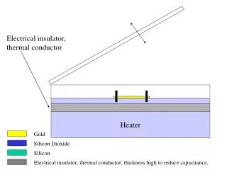
EnclosureNeeds & Specifications • Material (6061 Aluminum Alloy, 316 Stainless Steel) • Size (Minimize) • Mass (<0.450 lb) • Mounting (Enclosure, PCB, Connectors*) • Vibrations (23.1 G’s Random Vibration) • Thermal (-40°C to +55°C) • Vacuum Environment • Ventilation* (<1 psi/s) • Outgassing • Torque on Screws* • EMI Leakage* (<100 kHz) KGCOE Multidisciplinary Senior Design
EnclosureAssembly Model KGCOE Multidisciplinary Senior Design
EnclosureAssembly Model: Exploded View KGCOE Multidisciplinary Senior Design
EnclosureSpecifications Met • Material: • 6061-T6511 Aluminum Alloy (Top & Bottom Parts) • Type 316 Stainless Steel (Machine Screws) • Total Size: 3.50” x 2.875” x 1.00” • Size of the PCB with the Accelerometer: 3.0” x 2.0” x 0.563” • Total Mass: 0.4317 lb • 4.06% below the 0.450 lb limit • Enclosure Mounting: • Flat Plate & Cylinder (R > 18”), dmax< 3/32” • PCB Mounting: • Five (5) 2-56 Machine Screws KGCOE Multidisciplinary Senior Design
EnclosureSpecifications Not Met • Partially Met • Connector Mounting • Vacuum Environment • Ventilation • Outgassing • Not Met • Torque on Screws • EMI Leakage KGCOE Multidisciplinary Senior Design
EnclosureDesign Analysis: Strengths & Weaknesses • Strengths • Scalable to Varying Sizes of the PCB • Easy to Machine • Two (2) Pieces • Low Cost of Materials • Easily Assembled • Weaknesses • Excess Weight • 1/8” thickness for machining • Connector Mounting • Mating connectors are not secured KGCOE Multidisciplinary Senior Design
EnclosureDesign Analysis: Potential Improvements • Decrease Weight • Decrease the thickness to 1/16” or 3/32” from 1/8” • Change the strew type from 4-40 to 2-56 • Connector Mounting • Add component to secure mating connectors • Account for Ventilation • Add ventilation slot • Account for EMI Leakage • Minimum thickness • Account for the Torque on Screws • Verify minimum screw type KGCOE Multidisciplinary Senior Design
Graphical User InterfaceOverview • System required a simple computer interface • Needed to be able to control DSP’s and send commands • Easily readable and intuitive • Be able to control multiple parameters • Be able to communicate via Serial Port • Able to control 256 DSP’s KGCOE Multidisciplinary Senior Design
Graphical User InterfaceLabView • LabView was chosen mainly because of its ease of use, and familiarity between the team members • LabView allows us to easily create a nice GUI with multiple features • LabView is also scalable, allows us to add or change features easily without rewriting all of the programming KGCOE Multidisciplinary Senior Design
Graphical User InterfaceSpecifications • Communicate over serial port (RS232) • Ability to see heater state status and telemetry information • Ability to set and change temperature set points • Ability to chose between 255 slaves to upload temperature KGCOE Multidisciplinary Senior Design
Graphical User InterfaceProgramming • Programming started with communication over serial • Building blocks for the project were added on top • Each requirement or functionality that was needed was researched then implemented • Problems that arose were quickly dealt with by research KGCOE Multidisciplinary Senior Design
Graphical User InterfaceProgramming/Development • Message Creation • Messages were created using loops and numerical to string identifiers. • Labview sends out 24 bits, which gets converted to 3 ASCII characters • Message Contents • Message contains all elements needed to communicate with DSP • Slave ID gets transmitted first, control bits 2nd, and temperature last • The control bits relate to controls on the front panel that allow the user to manipulate the message and retrieve different data KGCOE Multidisciplinary Senior Design
Graphical User InterfaceProgramming/Development • Structures • All Labview programming is grouped within loop structures so data and set points can be updated continuously. • Different structures exist for different functionality. • Initialization of slaves, Continuous message sending, Message building • Some key building blocks are : Steinhart-Hart function, Binary number creation, Voltage readings, Serial port open/close KGCOE Multidisciplinary Senior Design
Graphical User InterfaceFront Panel KGCOE Multidisciplinary Senior Design
Graphical User InterfaceSpecs Met/ Not Met • Met • Ability to communicate over serial • Ability to send and receive data from DSP • Ability to control temperature and control bits • Has visual indicators • Not Met • Simplicity of GUI KGCOE Multidisciplinary Senior Design
Graphical User InterfaceStrengths/Weaknesses • Strengths • Very Powerful • Has lots of Error Checking and Debugging • Easily Understood • Weaknesses • Computer resource intensive • Complex changes take time KGCOE Multidisciplinary Senior Design
Graphical User InterfacePotential Improvements • Improvements • Make front panel more visually appealing • Revise and improve looping • Create simpler ways to do programming KGCOE Multidisciplinary Senior Design
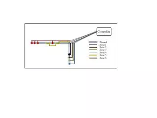
CommunicationsOverview KGCOE Multidisciplinary Senior Design
PC to Master Communications Overview • Communication between Master DSP and Graphical User Interface (GUI) must occur over SCI • Protocol must be able to incorporate the many needs of the User • Master must generate a new message for the ‘slave’ DSPs after receiving a message from GUI. • After receiving a response from the appropriate slave, the master DSP must generate a new message to send back to GUI KGCOE Multidisciplinary Senior Design
PC to Master Communications SCI Protocol • SCI protocol (LabView to Master) • 3 Pins - Transmit, Receive, Ground • 3 Transmissions - 12 Bit Each • 1 Start Bit • 8 Data Bits(Slave ID, Temp. Bits, and Ctrl Bits) • 1 Parity Bit (Eliminates Checksum) • 2 End Bits KGCOE Multidisciplinary Senior Design
PC to Master Communications Objectives • The SCI message was received and transmitted back using an interrupt routine using the RX buffer and TX buffer in the EzDSP. • A circular buffer routine was utilized to prevent overriding incoming messages from LabView. • The Master to DSP message also included five telemetry pins, mainly used for debugging. • Messages from LabView were appended to include start bits, transmit/receive bit, error bit, and check sum bits. KGCOE Multidisciplinary Senior Design
PC to Master Communications Specifications Met/Unmet • Specs Met • Ability to communicate from/to GUI via serial port • Ability to communicate to/from the slaves and to retrieve information from the HHC • The use of an interrupt service routine for transmitting and receiving • Unmet Specs • 20ms total communication time KGCOE Multidisciplinary Senior Design
PC to Master Communications Strengths and Weaknesses • Strengths • The user can continuously ask the master to report data from any particular slave and see it updating in real time. • The protocol is reliably able to handle all of the user’s needs. • Weaknesses • Cannot guarantee a complete and/or correct message is sent all the time because of SCI • TCP for example, has the ability to automatically resend messages to ensure proper transmission to the receiver. KGCOE Multidisciplinary Senior Design
PC to Master CommunicationsPotential Improvements • A more reliable protocol instead of SCI • In order to better handle errors and ensure proper transmission KGCOE Multidisciplinary Senior Design
Master to Slave CommunicationNeeds • Master DSP communicates with up to 256 slaves over the heater power bus. No dedicated communication lines are used. • One master, multiple slave design. • DSPs communicate by a half-duplex BFSK technique. KGCOE Multidisciplinary Senior Design
Master to Slave Communication Modulation/Demodulation • A sine wave is generated from a binary string using the HRPWM and a passive low pass filter. • The sine wave is transmitted over the DC power bus. • The sine wave is then demodulated back into binary using the ADC with a digital filter. • The Goertzel Algorithm was used to implement the digital filter. KGCOE Multidisciplinary Senior Design
Master to Slave CommunicationProtocol • BFSK Protocol (Master to Slave) • Bi-directional, half-duplex (only slave or master can talk at one time) • Bit by bit transmission • Different frequencies for ‘1’ and ‘0’ (in order to meet the 20 ms spec, min. freq = 5kHz; 200 us/bit) • ‘0’ frequency = 62.5 kHz • ‘1’ frequency = 78kHz • No activity on line means no signal KGCOE Multidisciplinary Senior Design
Master to Slave Communication Protocol • 40 Bit Transmission • 2 Start Bits • 6 Checksum Bits • 12 Data (temp) Bits • 6 Control Bits (read/set, temp/htr state, etc.) • 5 Telemetry Pins • 8 Bits for Slave ID • 1 End Bit KGCOE Multidisciplinary Senior Design
Master to Slave Communication Interface Electronics • Coupling transformer to couple to AC and DC components. • Capacitor along with transformer used to create a high pass filter. • Allows us to create a sine wave on power bus without disturbing the operation of the heaters. KGCOE Multidisciplinary Senior Design
Master to Slave Communication Strengths and Weaknesses • Strengths • Used software techniques in the DSP to do the modulation and demodulation rather than using external hardware. • Flexible: different frequency/bandwidth combinations possible. • Weaknesses • Each slave added creates a parallel resistance so a larger and larger signal is needed for each slave added. • We don’t check to see if a message is good until a complete message is received. • Half Duplex only, can only send or receive at one time. • Reliability could be improved. KGCOE Multidisciplinary Senior Design
Master to Slave Communication Specifications • Master to slave communication time 20ms • Did not meet, actual communication time ~200ms • Bandwidth < 300KHz • Met, Bandwidth < 90Khz • Bit error rate 1e-6 • Did not meet, berundermined but higher than 1e-6 • Signal to noise ratio -40db • Did not meet, snr is around 10db • Amplitude < 10mVpp • Did not meet, Amplitude ~ 1Vpp KGCOE Multidisciplinary Senior Design
Master to Slave Communication How could these be improved? • Master to slave communication time 20ms • Reduce code size by splitting up master and slave code • Used external hardware to generate and detect sine wave • Bit error rate 1e-6 • Improve synchronization between master and slave Goertzel. • Signal to noise ratio -40db • Longer transmissions per bit, raise the bandwidth • Amplitude < 10mVpp • Output smaller signal and then amplify it KGCOE Multidisciplinary Senior Design
Closing Comments • Special Thanks • Margaret Bailey, Jerome Barczykowski, SohailDianat, Christopher Hoople, Marca Lam, Chuck Moon, Jay Radhakrishnan, Scott Reardon, George Slack, Perry Voyer, Christianna Walter and John Wellin • Questions and/or Comments KGCOE Multidisciplinary Senior Design