Download
1 / 25
250 likes | 441 Vues
Deformation & damage of lead-free solder joints. COST 531 Final Meeting, 17th-18th May 2007, Vienna J. Cugnoni 1 , J. Botsis 1 , V. Sivasubramaniam 2 , J. Janczak-Rusch 2 1 Lab. Applied Mechanics & Reliability, EPFL, Switzerland 2 Füge- und Grenzflächentechnologie, EMPA, Switzerland.

E N D
Deformation & damage of lead-free solder joints COST 531 Final Meeting, 17th-18th May 2007, Vienna J. Cugnoni1, J. Botsis1, V. Sivasubramaniam2, J. Janczak-Rusch2 1 Lab. Applied Mechanics & Reliability, EPFL, Switzerland 2 Füge- und Grenzflächentechnologie, EMPA, Switzerland
Outline • Overview of the project: • Global goals & achievements • Methods & developments: • Experimental techniques • Modelling • Key results • Elasto-plastic characterization of SAC405 • Constraining & size effects • Ductile failure: effect of voids • Future • Bridging the length scales & the disciplines
Nature of Irreversible Deformations Objectives Global Project Interface Micro Structure ConstitutiveEquations Thermo-mechanical History Size / ConstrainingEffects Manufacturing Deformation & damage of lead-free solder joints • Size & constraining effects • Tensile / shear joints • Effect of microstructure: • Effect of porosity content • Failure mechanisms: • Ductile fracture • Studied system: • SAC 405 / Cu substrates ?
Designof Experiments Elasto-plastic characterization of SAC 405 Effects of voids on the reliability of joints Experimental OpticalStrainMeasurement Micro Structure Analysis Constitutive LawType Finite Element Model Modelling Effects of Constraints Investigations on Size Effects Inverse Num. / Exp.Identification Methods & developments: overview
Nature of Irreversible Deformations Global Project Interface Micro Structure ConstitutiveEquations Thermo-mechanical History Size / ConstrainingEffects Manufacturing Key results: overview
Thoughts about the future…. Short term: • Time / temperature dependent properties. • Interfacial failure: cohesive elements Mid-Long term: Bridging the length scales & disciplines Thermodynamics, phase diagrams Meso Solidification /diffusion simulation ? Diffusion, interfaces, solidification, microstructure Micro Homogenization Continuum mechanics, damage, fracture… Macro Need more transversal research !!
9.5 mm 8 mm 2 mm g 1 mm t 4 mm w L Tensile & shear specimens Tensile specimenL=120 mm, w=20 mm, t=1mm, g=[0.25, 0.5, 0.75, 1.2, 2.4] mm Solder cross section = 20x1 mm2 Shear specimenL=120mm, joint cross section=2x2 mm2 Optimized for stress uniformity & simple manufacturing thickness=2mm
Digital Image Correlation Why optical strain measurements?? • non-invasive measurements at a small scale DIC algorithms developments: • Tensile joints: • Small strains, small translations • High accuracy is needed • Spatial Correlation with cubic spline resampling • Shear joints: • Extremely large strains, large displacement • Need excellent robustness • Incremental FFT-based correlation Advantages / Drawbacks + Versatile & simple to setup + Robust in most cases - Resolution limited by pixel size - Need a random pattern 4 mm
ESPI measurements (STSM, D. Karalekas) Work done with Dr.Karalekas,Univ. Piraeus, Greece during a STSM at EPFL Advantages: • Sensitivity independant from magnification: excellent for global observations • Full field measurement Drawbacks: • Decorrelation • Problems with creep tests Application: • Evaluate boundary conditions • Full field displacement measurement on assemblies 20 mm
Finite Element modelling Modelling? why?? • Models have the power of generalization of knowledge FE models Advantages: • Versatility: Complex geometries, multi-components, multi-physics • Ability to extrapolate knowledge gained on simple test cases to much more complex designs & geometries !! • Multi-scale modelling (homogenization) Drawback: • Requires an extensive & reliable set of parameters => huge characterization task Combining Experiments & Numerical simulation is of prime importance
Inverse num.-exp. identification In-situ characterization of constitutive parameters Experimental SpecimenProduction TensileTest (DIC) Experimental Load – Displacement / Stress-Strain response Global / local responseof the specimen Geometric &structural effects Identification Loop Optimization (Least Square Fitting) Modelling parameters:Constitutive law, failure model Geometry & BoundaryConditions FEM Simulated Load – Displacement / Stress-Strain response Numerical Simulations
Rigid substrates: - impose lateral stresses at the interfaces - hydrostatic stresses => apparent hardening => constraining effects Plastic deformation of solder: - constant volume => solder shrinks in lateral directions Solder joint in tension: - stiff elastic substrates - plastic solder (n~=0.5) Constraints in tensile solder joints
Parametric FE study: Results => Constraining effects are due to the the triaxiality (hydrostatic part) of the stress field in the solder induced by the substrate
Parametric FE study: Results Constraining effects are inversely proportionnal to the gap to thickness ratio G in tensile joints
Shear: constraining effects Parametric FE simulation of shear joint response Pure shear = isochoric deformation => no significant effects of constraints !!
Shear: Gap – ultimate stress relationship Shear: No significant effect of solder gap on ultimate stress
Size effects: Tensile & Shear solder joints
Identified elasto-plastic law / size effects Tensile joints Mechanical properties decreasing for smaller joints: combination of scale effects & porosity Manufacturing process is also size dependant
Identified elasto-plastic law / size effects Shear joints Size effect • Tensile / shear joints: • similar elasto-plastic behaviours • - similar size effects (manufacturing?)
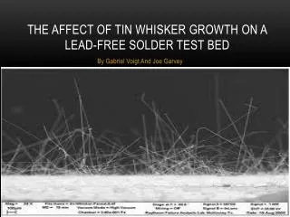
2.4mm 0.7mm 0.5mm (vacuum) Microstructure & Fractography Microstructure before testing Fractography • Pores: • created during manufacturing and grow with plastic deformation • introduces large scatter in experimental data => model void !! • If porosity cannot be eliminated • => Include it in models as a « random » variable
Evolution of porosity Growth Nucleation Porous metal plasticity: Gurson-Tvergaard model Porosity content is an internal variable of the model: f= density ratio = 1- void_fraction Effect of voids Yield surface Hydrostatic pressure Yield function without pores
Changes in initial porosity % Shear joint response & porous metal plasticity Plastic Yielding Void growth Void nucleation Ult. strain
Ductile failure simulation Void growth Plastic Yielding Void nucleation Ult. strain • Porous metal plasticity model can • Predict the progressive ductile failure of metal up to rupture • Simulate shear band formation & localization • Introducing « random » initial porosity => statistical estimate of the failure strain in a given assembly