Download
1 / 43
850 likes | 1.85k Vues
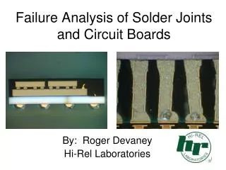
Failure Analysis of Solder Joints and Circuit Boards. By: Roger Devaney Hi-Rel Laboratories. Typical types of solder joints. PWB ILCs still cause many failures. Laminate stack up. A layer of uncured prepreg is placed on each side.

E N D
Failure Analysis of Solder Joints and Circuit Boards By: Roger Devaney Hi-Rel Laboratories
Laminate stack up • A layer of uncured prepreg is placed on each side. • Outer cores with the internal layers patterned are laid up in alignment jig. • Layers are laminated under heat and pressure.
Laminate stack • Laminate is now a single unified structure
Via holes are drilled • Precision tungsten carbide drill bits are used to drill holes where needed. • Drilling results in a damaged layer that must be removed by etching.
Drill damage removed by etching • A “witches brew” of HF and H2SO4 is used to removed damaged glass fibers and smeared epoxy resin. • Very critical step to ensure via reliability.
Electroless copper plating • Electroless copper plating covers entire board, especially drilled hole walls. • Provides base for subsequent electrolytic copper.
Electrolytic copper plating • This is the conductor layer of copper applied over the electroless copper.
Traditional Sn-Pb eutectic joints Pb free solder joints
Head-on pillow (HoP) BGA joint • HoP is caused by: • Solder paste printing and rheology issues • Reflow temperature uneven or too low • Board warping during reflow • Process out of control
Dye & Pry Testing • This is a quick/inexpensive way to look for cracked or non-wetted BGA joints. • Allows for simultaneous inspection of all of the joints at once. • Materials and equipment needed are readily available
Dye & Pry Test Procedure • Cut out device to be tested from the PCB • Clean flux from under device and bake dry • Immerse part in Dykem Red fluid under partial vacuum • Shake off excess dye and bake dry • Pry off BGA using pliers and/or vise and screwdriver • Inspect for any dye on separated joints
Thermal Fatigue • When the assembly is temperature or power cycled the different materials in the attach want to expand/contract according to their CTE’s. • The attach material is (usually) the weakest point in the assembly so it is expected to absorb the stresses of thermal mismatch by yielding in creep. • The amount of creep an attach can endure is limited, then it will begin to crack.
Black Pad failure • This only occurs on Electroless Nickel, Immersion Gold (ENIG) finished devices & boards: • ENIG has come into wide use with the advent of RoHS and the lead-free solders • The ENIG process actually “corrodes” the top layer of the electroless nickel-phosphorous as the gold is deposited in a displacement reaction • This displacement reaction concentrates the phosphorous in the upper nickel layer right under the gold, and sometimes gets out of control • Normal electroless nickel will have 8-12% P, but black pad regions can have up to 30% P! • During soldering the very thin gold layer dissolves instantly leaving the solder on top of the corroded, high P, nickel layer. • This can result in dewetting and/or poor solder joint strength • When the solder joints fail, the corroded nickel layer is exposed and it is usually black in appearance; hence the name…