Download
1 / 15
150 likes | 267 Vues
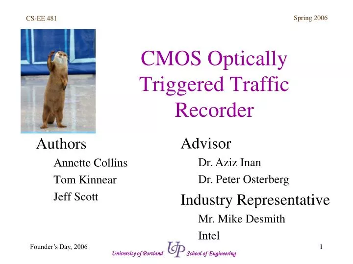
This paper discusses the design and implementation of a CMOS optically triggered traffic recorder aimed at analyzing room usage and traffic flow. The device incorporates optical triggering methods and custom CMOS ICs to automate building management. This system can function independently or interact with a PC to log data and control lighting. The project covers its functional specifications, design methods, results from prototype testing, and conclusions drawn about its performance, including solutions to encountered issues and potential improvements for future development.

E N D
CMOS Optically Triggered Traffic Recorder Authors Annette Collins Tom Kinnear Jeff Scott • Advisor • Dr. Aziz Inan • Dr. Peter Osterberg • Industry Representative • Mr. Mike Desmith • Intel University of Portland School of Engineering
Agenda Introduction Annette Background Tom Methods Tom Results Jeff Conclusions Annette Demonstration Tom University of Portland School of Engineering
Introduction What is it? People Counter Room usage and traffic analysis tool What is the purpose? Building automation Usage Analysis University of Portland School of Engineering
Introduction Assumptions No Intentional Disruptions Single Person Doorway Digital Sensor Output University of Portland School of Engineering
Background Technologies Optical triggering methods CMOS VLSI circuit design RS-232 Serial Link Linux C programming University of Portland School of Engineering
Background Functional Specifications Room & Day counters 2-way communication with PC Data logging via PC Operate as stand-alone unit (no PC) Ability to control room lighting 2 Custom CMOS ICs University of Portland School of Engineering
Methods Top Down Design Determined functional specifications Created block diagrams Created 4 distinct parts Counters, Direction Sensors, Light Controller, Off Chip Logic Hierarchical Design for each part Integrated parts University of Portland School of Engineering
Methods Top Down Design Software Modeling B2Logic, Ledit Programmed CPLDs for Macromodel Assembled prototype Debugged circuitry University of Portland School of Engineering
Results How it Works... University of Portland School of Engineering
Results University of Portland School of Engineering
Results It Works! Problems & Obstacles Wrap around ‘bug’ PC Interfacing Heat Room Usage Report University of Portland School of Engineering
Results University of Portland School of Engineering
Conclusions Recap Improvements Fix the wrap-around bug Heat Design sensors to operate on +5VDC Shrink hardware Consider IEEE 802.3 Ethernet Connection University of Portland School of Engineering
Conclusions Special Thanks Mr. Mike Desmith, Intel Dr. Aziz Inan Dr. Peter Osterberg Sandra Ressel MOSIS Foundation University of Portland School of Engineering
Demonstration University of Portland School of Engineering