Download

1 / 34
350 likes | 552 Vues
Hydraulic Servo and Related Systems. Chris Paredis / Wayne J. Book G.W. Woodruff School of Mechanical Engineering Georgia Institute of Technology. Lecture Overview. Why fluid power? Basic fluid-power circuits Simple dynamic model Efficiency considerations Advanced metering methods.

E N D
Hydraulic Servo andRelated Systems Chris Paredis / Wayne J. Book G.W. Woodruff School of Mechanical Engineering Georgia Institute of Technology
Lecture Overview • Why fluid power? • Basic fluid-power circuits • Simple dynamic model • Efficiency considerations • Advanced metering methods
Hydraulics is Especially critical to the Mobile Equipment Industry
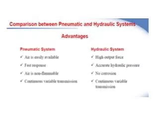
The Strengths of Fluid Power(Hydraulic, to a lesser extent pneumatic) • High force at moderate speed • High power density at point of action • Fluid removes waste heat • Prime mover is removed from point of action • Conditioned power can be routed in flexible a fashion • Potentially “Stiff” position control • Controllable either electrically or manually • Resulting high bandwidth motion control at high forces • NO SUBSTITUTE FOR MANY HEAVY APPLICATIONS
Difficulties with Fluid Power • Possible leakage • Noise generated by pumps and transmitted by lines • Energy loss due to fluid flows • Expensive in some applications • Susceptibility of working fluid to contamination • Lack of understanding of recently graduated practicing engineers • Multidisciplinary • Cost of laboratories • Displaced in curriculum by more recent technologies
Voltage-Current System Overview Electric or IC prime mover Trans-mission line & valve RPM Torque Flow Press. Flow Press. RPM-Torque Motor or cylinder orVelocity-Force Pump • The system consists of a series of transformation of power variables • Power is either converted to another useful form or waste heat • Impedance is modified(unit force/unit flow) • Power is controlled • Function is achieved Coupling mechanism orVelocity-Force RPM-Torque Load
Simple open-loop open-center circuit cylinder Actuating solenoid Spring return Pressure relief valve 4-way, 3 position valve filter Fixed displacement pump Fluid tank or reservoir
Simple open-loop closed-center circuit Which is betterin this case? Open- orclosed center?
Closed-loop (hydrostatic) system Motor Check valve Variable displacement reversible pump Drain or auxiliary line
Basic Operation of the Servo Valve(single stage) Flow enters Flow exits Torque motor moves spool left Positive motor rotation
Basic Operation of the Servo Valve(single stage) Flow enters Flow exits Torque motor moves spool right Negative motor rotation
p0 ps p0 x p2, q2 p1, q1 4 Way Proportional Spool Valve Model • Spool assumptions • No leakage,equal actuator areas • Sharp edged, steady flow • Opening area proportional to x • Symmetrical • Return pressure is zero • Zero overlap • Fluid assumptions • Incompressible • Mass density
p0 ps p0 x p2, q2 p1, q1 Dynamic Equations (cont.)
q1 Change in volume y Net area Ap Change in density Dynamic Equations: the Actuator • If truly incompressible: • Specification of flow without a response in pressure brings a causality problem • For example, if the piston has mass, and flow can change instantaneously, infinite force is required for infinite acceleration • Need to account for change of density and compliance of walls of cylinder and tubes
Compressibility of Fluids and Elasticity of Walls For the pure definition, the volume is fixed. More useful here is an effective bulk modulus that includes expansion of the walls and compression of entrained gasses Using this to solve for the change in pressure
q v 1/A q p dv/dt k dt A /m Choices for modeling the hydraulic actuator With no compliance or compressibility we get actuator velocity v as With compliance and/or compressibility combined into a factor k And with moving mass m
Controls Issues: Summary • Nonlinearities • Good velocity control • Velocity approximately proportional to valve position • Bandwidth determined by compressibility and spool dynamics • How about position control? • How about force control?
Lecture Overview • Why fluid power? • Basic fluid-power circuits • Simple dynamic model • Efficiency considerations • Advanced metering methods
p Q Generated Power Useful Power Open-loop open-center circuit – Revisited • Energy efficiency?
Pressure-Compensated Load-Sensing Circuit EnergySavings p Q Generated Power Useful Power
Pump x F Ksb Ksa B A Kbt Kat Tank Check Valve Independent Metering: Introduction Independent Metering Configuration
Pump F x Ksb Ksa B A Kbt Kat Tank Check Valve Powered Extension Mode Advantages of Independent Metering: Metering Modes • Energy saving potential: Regenerative flow.
Pump F x Ksb Ksa B A Kbt Kat Tank Check Valve High Side Regeneration Extension Advantages of Independent Metering: Metering Modes • Energy saving potential: Regenerative flow.
Pump F x Ksb Ksa B A Kbt Kat Tank Check Valve Low Side Regeneration Extension Advantages of Independent Metering: Metering Modes • Energy saving potential: Regenerative flow.
Pump F x Ksb Ksa B A Kbt Kat Tank Check Valve Powered Retraction Advantages of Independent Metering: Metering Modes • Energy saving potential: Regenerative flow.
Pump F Ksb Ksa B A Kbt Kat Tank Check Valve Low Side Regeneration Retraction Advantages of Independent Metering: Metering Modes • Energy saving potential: Regenerative flow.
Advantages of Independent Metering: Metering Modes • Energy saving potential: Regenerative flow. Regeneration flow can be defined as pumping the fluid from one chamber to the other to achieve motion control of the load with using no or minimum flow from the pump.
Summary • Main advantage of fluid power: • Very high forces/torques at moderate speed • Very high power density at point of action • Challenges: • Energy efficiency – hot research topic • Compactness (including prime mover) • User friendliness (leakage, noise, etc.)
References • Norvelle, F.D. Fluid Power Control Systems, Prentice Hall, 2000. • Fitch, E.C. and Hong I.T. Hydraulic Component Design and Selection, BarDyne, Stillwater, OK, 2001. • Cundiff, J.S. Fluid Power Circuits and Controls, CRC Press, Boca Raton, FL, 2002. • Merritt, H.E. Hydraulic Control Systems, John Wiley and Sons, New York, 1967. • Fluid Power Design Engineers Handbook, Parker Hannifin Company (various editions).