Understanding Multicycle Datapath and Control Path Design in Microprocessors
This document discusses the construction of multicycle datapaths and control paths for microprocessors, highlighting the limitations of single-cycle datapaths. It outlines how fixed clock cycles can hinder performance by forcing all instructions to operate within the longest path constraints. Techniques to implement shorter clock cycles through multicycle designs are explored, along with the instruction fetching and execution process. The importance of control unit design for effective operation is emphasized, detailing the necessary signal flow for various instruction types.

Understanding Multicycle Datapath and Control Path Design in Microprocessors
E N D
Presentation Transcript
CMPUT329 - Fall 2003 TopicI: Building a Multicycle Data Path and a Control Path for a Microprocessor José Nelson Amaral CMPUT 329 - Computer Organization and Architecture II
Reading Material(optional) Patterson, David A., and Hennessy, John L., Computer Organization & Design: The Hardware/Software Interface, San Mateo, CA: Morgan Kaufmann Pub., 1994. Chapter 5 Appendix B Appendix C CMPUT 329 - Computer Organization and Architecture II
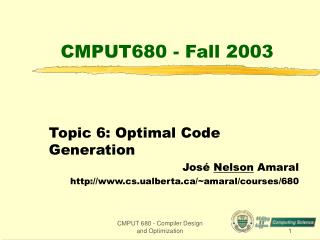
What is Wrong with the Single Cycle Datapath • The clock cycle must have the same length for every instruction • Therefore the clock cycle cannot be shorter than the longest possible path • In our example, this path is the load instruction, it uses: • the instruction memory, • the register file, • the ALU, • the data memory, and • the register file. CMPUT 329 - Computer Organization and Architecture II
What is Wrong with the Single Cycle Datapath • If we consider a machine with more complex instructions (p.e., floating-point arithmetics), or more powerful addressing modes, the single cycle penalty is unnaceptable. • The solution is to adopt a design with shorter clock cycles, but that requires multiple clock cycles per instruction. CMPUT 329 - Computer Organization and Architecture II
PC 0 0 I[25-21] M u x M u x Read register 1 Read address Instruction [31-26] 1 1 Read data 1 I[20-16] Zero Read register 2 Memory 0 Write address ALU result M u x Instruction [25-0] Write register 0 1 2 3 Read data 2 1 ALU MemData M u x Instruction register 4 Write data Write data [15-11] Registers 0 M u x 1 32 Sign ext. I[15-0] Shift left 2 16 A Multiple Cycle Datapath CMPUT 329 - Computer Organization and Architecture II
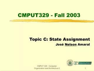
The Jump Instruction j loop Concatenate the 4 most significant bits of the PC with the 26 least significant bits of the IR[25-0] field of the instruction code and shift the result by two. Write the resulting value in the PC. PC concat(PC[31-28],IR[25-0])<<2 OpCode address 2 10000 25 0 31 26 000010 00 0000 0000 0001 0011 1001 0000 I-Type Instruction Format CMPUT 329 - Computer Organization and Architecture II
Values to be written into the PC. Three possible values can be written into the PC according to the instruction executed: For taken branches: PC PC + 4 + (sign-extend(IR[15-0]) << 2) For jumps: PC concat(PC[31-28],IR[25-0])<<2 For all other instructions: PC PC + 4 CMPUT 329 - Computer Organization and Architecture II
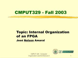
Steps to Execute EachInstruction Type CMPUT 329 - Computer Organization and Architecture II
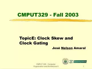
0 1 2 M u x 0 0 M u x M u x 1 1 0 M u x 0 1 2 3 1 M u x 0 M u x 1 16 26 32 4 Target Conc/ Shift left 2 PC I[25-21] Read register 1 Read address Instruction [31-26] Read data 1 I[20-16] Zero Read register 2 Memory Write address ALU result Instruction [25-0] Write register Read data 2 ALU MemData Instruction register 4 Write data Write data [15-11] Registers 32 Sign ext. I[15-0] Shift left 2
0 1 2 M u x 0 0 M u x M u x 1 1 0 M u x 0 1 2 3 1 M u x 0 M u x 1 26 32 16 32 4 PCSource TargetWrite Target Conc/ Shift left 2 PcWrite MemRead RegDst MemWrite ALUSelA IorD IRWrite MemtoReg RegWrite PC I[25-21] Read register 1 Read address Instruction [31-26] Read data 1 I[20-16] Zero Read register 2 Memory ALUSelB Write address ALU result Instruction [25-0] Write register Read data 2 ALU MemData Instruction register 4 Write data Write data [15-11] Registers 32 ALU control Sign ext. I[15-0] Shift left 2 ALUOp
0 1 2 M u x 0 0 M u x M u x 1 1 0 M u x 0 1 2 3 1 M u x 32 32 16 26 4 ALUOp PcWrite Control Unit PcWriteCond PCSource IorD ALUSelA MemRead TargetWrite RegWrite MemWrite Target IRWrite MemtoReg ALUSelB RegDst Conc/ Shift left 2 PC I[25-21] Read register 1 Read address Instruction [31-26] Read data 1 I[20-16] Zero Read register 2 Memory Write address ALU result Instruction [25-0] Write register Read data 2 ALU MemData Instruction register 4 Write data Write data [15-11] Registers 0 M u x 1 32 ALU control Sign ext. I[15-0] Shift left 2
Designing the Control Unit for the Multicycle Datapath Instruction Fetch Instruction Decode Load + Store R-type Branch Jump Address Computation Execution Branch Completion Jump Completion Store Load Memory Read Memory Write R-Type Completion Write Back CMPUT 329 - Computer Organization and Architecture II
MemRead ALUSelA=0 IorD=0 IRWrite ALUSelB=01 ALUOp=00 PCWrite PCSource=00 ALUSelA=0 ALUSelB=11 ALUOp=00 TargetWrite Load + Store R-type Branch Jump ALUSelA=1 ALUSelB=00 ALUOp=01 PCWriteCond PCSource=01 ALUSelA=1 ALUSelB=10 ALUOp=00 ALUSelA=1 ALUSelB=00 ALUOp=10 PCWrite PCSource=10 Store Load MemRead ALUSelA=1 IorD=1 ALUSelB=10 ALUOp=00 MemWrite ALUSelA=1 IorD=1 ALUSelB=10 ALUOp=00 ALUSelA=1 RegDst=1 RegWrite MemtoReg=0 ALUSelB=0 ALUOp=10 MemRead ALUSelA=1 IorD=1 RegWrite MemtoReg=1 RegDst=0 ALUSelB=10 ALUOp=00
Conventions All outputs that are not explictly asserted, are de-asserted, i.e., they must be specified for the correct operation of the datapath. If a signal that controls a multiplexor is not specified in a state, its value is don’t care, and the machine will work properly regardless of the input that is selected. CMPUT 329 - Computer Organization and Architecture II
Finite State Machine Controller Combinatorial Control Logic 17 Datapath Control Outputs 21 Outputs 10 Inputs Input from Instruction Register Opcode Field State Register CMPUT 329 - Computer Organization and Architecture II