Portable Sensing Field Device
520 likes | 870 Vues
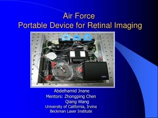
Portable Sensing Field Device. Group 4: Joel Yello Khoa Nguyen Dawson Brown Robert Pribyl. Project Introduction. Laser-Based Rangefinder IR Contactless Temperature Sensor Combine both functions into one light-weight, handheld device activated by a trigger .

Portable Sensing Field Device
E N D
Presentation Transcript
Portable Sensing Field Device Group 4: Joel Yello Khoa Nguyen Dawson Brown Robert Pribyl
Project Introduction • Laser-Based Rangefinder • IR Contactless Temperature Sensor • Combine both functions into one light-weight, handheld device activated by a trigger. • Provide simultaneous range and temperature readings via a 16x2 LCD output.
Motivation • New to optical systems • Group interest in laser technology and infrared technology • Combines 2 tools used every day • Lightweight • Small form-factor • Easy to read • Low power consumption • Time of Flight ranging is a challenge
Specifications • Ranging from 1-50 meters • +/- 1 meter accuracy in subsequent measurements • Temperature readings from 0-5 meters • +/- 2 degree accuracy in subsequent measurements • Device should weigh no more than 2.5 pounds for portability. • LCD display must switch between temperature and range readings on button press.
Power • Each individual part of our device operates in a range between 3.3 and 140 VDC. • Our high voltage supply needs to supply 140 volts. It supplies 400V at 12V, and through testing we have determined it can run 140V at ~5 volts. • Our device must remain portable, meaning we must choose a portable power source (i.e. batteries). • To obtain the different supply voltages to our silicon, our battery sources must be regulated. • Linear regulators are the cheapest and easiest to use for our application.
Power • Our project uses an op-amp that has dual rails, +- 5VDC. • Instead of buying an expensive buck-boost converter to obtain the negative voltage from the same source, we opted to use a secondary source and drive a negative voltage regulator from it.
Source Options Since we must use two batteries, one to supply the positive voltages, and one to supply the negative voltages, we have to consider the price and weight of making a battery pack of individual cells. In the end, two battery packs of any of the first three technologies becomes undesirable. We will use two 9V batteries.
Voltage Regulation • In order to power the different chips we have employed, we have to regulate our 9V sources to lower voltages in order to operate them.
Design Considerations • Methods of Ranging considered • SONAR (ultrasonic) • Cheapest to implement • Easy to use • Distance limited to less than 10m • RADAR • Can achieve very far distance readings • Does not bounce off all objects • LIDAR (Laser\infrared) • Best choice: Line of sight ranging and will reflect at least some light off almost all surfaces. • Our design will use the time of flight method
Avalanche Photodiode • Must be operated under high voltage (100V+) • Very sensitive photo-receiver • Advantages include: • Exploits the avalanche multiplication process for added gain • Ideal for a rangefinder • High speed operation • High quantum efficiency • Design considerations: • Terminal capacitance • Sensitive to ambient temperature changes • Exhibit measurable dark current
APD Selection • Main selection aspects included: • Low bias operation • Peak spectral sensitivity • Low price • Max dark current • Temperature coefficient • Selected mid-range Hamamtsu S2381
Temperature effects on S2381 • As the ambient temperature increases, the voltage required to maintain constant gain must increase. • We are operating with M at 100.
High Voltage DC-DC Converter • Decided to buy pre-made converter instead of building our own due to size goal. • Emco Q04 outputs 60-400V • Maximum output current of 1.25mA • Peak-peak output ripple less than .1% • Draws less than 100mA under full load at 12v input voltage. • As a cube of only 0.5 inches and a weight of just over 4 grams, the Q04 is ideal for portable applications.
Ambient Temperature Adjust • Control pin on HV supply must be adjusted to maintain constant gain. • Tmp275 – Digital output temperature sensor will be used to detect ambient temperature. • Eight addresses • Two wire serial interface using I2C • Capable of reading temperatures with a resolution of 0.0625°C • Temperature range of -40 to +125°C • As ambient temperature changes, analog output from MCU will change from 0-5V; directly changing the HV output.
Transimpedance Amplifier • Requirements • Must be very low noise • Must provide acceptable gain • Vo max 5 volts pk-pk • High speed response • TI OPA847 • BJT amplifier • High GBP: 3.9GHz • High slew rate 950V/us • Very low voltage noise of 0.85nV/√Hz • Since feedback capacitor is inversely proportional to resistance, an additional gain stage will be needed.
Circuit Schematic • Shown highlighted in yellow is a current source and input capacitance representing the APD. • Boxed in blue is the gain resistor of 12k and feedback capacitance used to control the frequency response. • The red box is the additional op-amp that serves as an extra gain stage to put the output voltage in the range of 1-5V.
Infrared Optical Filter • Required to block out unwanted wavelengths from entering system. • IR band-pass filter from Edmund optics. • Diameter of 25mm • CWL of 780nm • Same as output laser. • With a Pass-band of only 10nm; the filter is very precise
Laser Optics: PCX Lens • Edmund Optics: V-Coated 785nm • Maximum throughput at 785nm • Glass substrate, N-BK7 (RoHS compliant) • 125mm Focal Length • Longer Focal Length = More intense focal point
ACAM TDC-GP21 • Time to Digital Converter • Measures the time difference between 2 signals • Capable of implementing TOF laser ranging due to redundant circuitry and propagation delays. • Multiple clock signals capable of measuring 3ps intervals (3 mm) • QFN 32 package • SPI communication • Fire Pulse Generator • Output tied to laser module and START channel • Cost effective: $40.00 for a large increase in range
ATmega328 & Arduino Uno Board • 13 digital GPIO pins • 6 analog input pins • Can serve as digital GPIO • 16 MHz Crystal Oscillator • 5V and 3.3V output perfect for prototyping • Price: $35.00 • SPI and I2C compatible
Arduino Uno Environment • C-based programming • SPI Library (GP21 Communication) • I2C Library (TMP 275 Ambient Temp Sensor) • LCD Library (Hitachi HD 44780) • Extensive Support Community • Online Tutorials • Limitations with SPI communication require new functions to be written
Arduino-GP21 Prototyping • 4 Wire SPI connection • Declare new Slave Select Line for GP21 • 3.3V Supply from Arduino to TDC
LCD Prototyping • 4 Wire interface for data transfer (D2-D5) • 2 Wire interface for Enable and R/W configuration (D6-D7) • 5V supplied by Arduino to power LCD and backlight
Prototyping GP21, Arduino, LCD • LCD: Fully Functioning • GP21: Re-writing the functions needed to communicate with the registers including: readReg() writeReg() TOeeprom() FROMeeprom() readResult() fetchStatus()
IR Temperature Function • Temperature need to be control and monitor engineering application like cooling, heating, drying, and storage. • Increase ability portable sensing field device by giving temperature measuring function. • Considered methods: • * Mechanical • * Thermo-junctive • * Thermo-resistive • * Infrared radiation • Infrared radiation
Infrared Radiation - Reasons • Noncontact measurement • Require small energy • Long wavelength –transmitted better through various medium. • It could emit to all kinds of bodies.
Detectors • Consider types: + Quantum: Expensive + Thermal: Thermocouple Thermopile Bolometer Micro Bolometer * Thermopile: affordable, small, and accurate Digital detector : MLX90614 Analog detector: MLX90247 , ZTP – 135SR
ZTP-135SR Infrared wavelength: 5 цm to 15 цm
FEATURES • Small-size sensor (TO-46 package) • Included ambient temperature (thermistor) sensor for compensation • High sensitivity • Fast response time • Low cost • Consists of thermo-elements, flat IR filter • Thermistor of temperature compensation in a hermetically-sealed package. • Variety of filters available to help maximize performance in specific applications
Op-amp Chopper – AD8628 • Lowest Auto-zero Amplifier Noise • Low Offset Voltage: 1 цV • Input Offset Drift: 0.02 цV/C • Very Low Input Bias Current: • Low Supply Current: 1.0 mA • Overload Recovery Time: 10 цs • No External Components Required • Rail to Rail Input and Output Swing • 5V Single-Supply Operation
IR Thermometer Optics • Single Fresnel Lens made of HDPE • Salvaged from porch-light lens • Cost-Effective Vs. Germanium or Silicon • Commonly used in low-cost PIR sensors and IR temperature guns
MLX90614 • Small size, low cost • High accuracy of 0.5ºC • Range -40ºC to 125ºC ambient temperature 70ºC to 382.19ºC object temperature. • SMBus compatible digital interface • Customizable PWM output for continuous reading • Sleep mode for reduced power consumption
Calibration • Range detect • Fresnel lens • Emissivity • EEPROM • Emissivity 0x04 • Base 0x0F • Filter 0x25
Challenges • Frequency stability with of the transimpedance amplifier • Interfacing TDC to APD module • Quantifying the delay of the laser module startup • Properly mounting the lens and filter so that its focal point is on the APD • Possibly using a different LCD for increased user experience • Enclosure issues