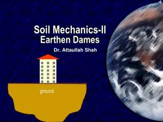
Soil Mechanics - II
261 likes | 919 Vues
Soil Mechanics - II. Practical Portion. Experiment No. 05. Determination of shear strength parameters (cohesion and angle of internal friction) by shear box test. Designation. ASTM D 3080-03. Scope.

Soil Mechanics - II
E N D
Presentation Transcript
Soil Mechanics - II Practical Portion
Experiment No. 05 Determination of shear strength parameters (cohesion and angle of internal friction) by shear box test.
Designation • ASTM D 3080-03
Scope • This test method covers the determination of shear strength of a soil sample under direct shear. • Test conditions including normal stress and moisture environment are selected which represent the field conditions being investigated. • This test method provides data useful in determining strength and deformation properties of cohesive soils. • The results of the test may be affected by the presence of soil or rock particles.
Apparatus • Shear Device • Shear Box • Triaxial Compression Chamber • Porous Inserts • Loading devices • Deformation Indicator • Shear force measurement device • Sample Extruder • Specimen Size Measurement Devices • Timer • Balances
Procedure • Place a soil specimen in a relatively flat box, which may be round or square (Fig.) • A normal load of specific (and constant) magnitude is applied • The box is "split" into two parts horizon- tally (see Fig.), and if half the box is held while the other half is pushed with sufficient force, the soil specimen will experience shear failure along horizontal surface A. • This procedure is carried out in a direct shear apparatus (Fig.), and the particular normal load and shear stress that produced shear failure are recorded. • The soil specimen is then removed from the shear box and discarded, and another specimen of the same soil sample is placed in the shear box. • A normal load differing from (either higher or lower than) the one used in the first test is applied to the second specimen, and a shearing force is again applied with sufficient magnitude to cause shear failure. • The normal load and shear stress that produced shear failure are recorded for the second test. • After failure remove the sample from the triaxial chamber and find out its moisture content for further calculations. • The procedure is repeated for the new specimen for a different (either higher or lower) lateral pressure. The axial load at failure and the lateral pressure are recorded for the second test.
Graph Preparation • The results of these two tests are plotted on a graph, with normal stress (which is the total normal load divided by the specimen’s cross-sectional area) along the abscissa and the shear stress that produced failure of the specimen along the ordinate (see Fig.). • The same scale must be used along both the abscissa and the ordinate. • A straight line drawn connecting these two plotted points, is extended to intersect the ordinate. • The angle between this straight line and a horizontal line ( in Fig.) is the angle of internal friction ( in Eq.), and the shear stress where the straight line inter- sects the ordinate (c in Fig.) is the cohesion [c in Eq.]. • These values of and c can be used in Eq. to determine the given soil’s shear strength for any load (i.e., for any effective inter granular normal pressure,). • Intheory, it is adequate to have only two points to define the straight- line relationship of Fig. Inpractice, however, it is better to have three (or more) such points through which the best-fitting straight line can be drawn.