Download
1 / 18
180 likes | 314 Vues
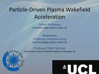
This study investigates the use of tunneling ionization in plasma wakefield accelerators (PWFA) to effectively boost energy in electron/positron colliders. We explore the concept of a "plasma afterburner," highlighting how large plasma wakefields can tunnel ionize neutral gases and facilitate the elimination of pre-ionization complexities. Using simulations from the OOPIC code, we examine different driver types, their wakefield characteristics, and compare ionization effects in colliders. Findings provide valuable insights into optimizing accelerator performance while reducing operational costs.

E N D
Ionization Physics in Plasma Wakefield Accelerators D. Bruhwiler,1D.A. Dimitrov,1 J.R. Cary,1, 2 W.P. Leemans,3 and E. Esarey,3 C. Nieter1 1. Tech-X Corporation 3. Lawrence Berkeley National Laboratory 2. University of Colorado Tech-X Corporation 5621 Arapahoe Ave., Suite A Boulder, Colorado 80303 http://www.txcorp.com • Work supported by US Dep’t. of Energy: • DE-FG03-02ER83557 (Tech-X, SBIR) • DE-FG02-01ER41178 (Tech-X, SciDAC) • DE-FG03-95ER40926 (U. Colorado) • DE-AC03-76SF00098 (LBNL & use of NERSC)
Motivation • The “plasma afterburner” concept: • suggests use of PWFA to double the energy of an e-/e+ collider • S. Lee, T. Katsouleas, P. Muggli, W. Mori, C. Joshi et al., Phys. Rev. ST Accel. Beams 5, 011001 (2002). • requires two PWFA modules, driven by e- and e+ beams • Field-induced tunneling ionization is a key effect • The large plasma wakefields can tunnel ionize neutral gasses • The self-fields of the drive beam can also tunnel ionize Li, Cs, etc. • Eliminates expense & complication of preionization • D. Bruhwiler, D.A. Dimitrov, J.R. Cary, E. Esarey, W.P. Leemans and R. Giacone, Phys. Plasmas 10 (2003), p. 2022. • It’s necessary to simulate e+ drivers as well • How does ideal pre-ionized case compare to tunnel-ionized case? • How do e- driven wakes compare to e+ wakes? • The parameters are taken from E-164x • D. Bruhwiler, D.A. Dimitrov, J.R. Cary, E. Esarey and W.P. Leemans, Proc. Part. Accel. Conf. (2003), p. 734.
The OOPIC Code & the IONPACK Library • OOPIC is a 2-D (x-y & r-z) time-explicit PIC code • developed at UC Berkeley, beginning in 1992 • J.P. Verboncoeur, A.B. Langdon and N.T. Gladd, Comp. Phys. Comm. 87 (1995), p. 199. • Tech-X and collaborators began working with the code in 1998 • D.L. Bruhwiler, R.E. Giacone, J.R. Cary, J.P. Verboncoeur, P. Mardahl, E. Esarey, W.P. Leemans and B. Shadwick, Phys. Rev. Special Topics - Accel. & Beams, 101302 (2001). • Available for MS Windows, Unix/Linux and also MacOS X • http://www.txcorp.com/products/OOPIC_Pro/ • IONPACK is a C library of ionization algorithms • Goal: provide ionization algorithms to all community codes • tunneling ionization (TI) • barrier suppression ionization (BSI), • electron-impact ionization and scattering at all energies • supports calls from Fortran 77/90/95 and C/C++ codes • Now being used with VORPAL (C++, 1D-3D, massively parallel)
Parameters for 2-D (r,z) “(SLC) Afterburner” Simulations(without tunneling ionization) • 50 GeV e- drive beam • sr=20 mm & sz=63 mm • 2x10¹⁰ e- in the bunch • r,z are normalized to le=282 mm • e- density is ne=1.4x1016 cm-3 • Grid size is Dz=Dr=7.5 mm • 34,000 beam ptcls (80 per cell) • 56,000 plasma ptcls (7 per cell) • Moving window is used • Particles & fields removed at left • Cold plasma enters at right
Tunneling Ionization Probability Rate • Adiabatic and quasi-classical approximations are used to calculate the probability rate for tunneling ionization: • Keldish, Sov. Phys. JETP 20, 1307 (1965). • Ammosov, Delone and Krainov, Sov. Phys. JETP 64, 1191 (1986). • Result is an ionization probability rate • Taken from Eq. (1) of ADK paper • Presented here in convenient units • W=1 would imply 100% ionization in 1 s, assuming constant E E is the local electric field magnitude xi is the ionization energy n* 3.69 Z / i1/2 [eV] is the “effective” principal quantum number Z is the charge state of the resulting ion (Z=1 for neutral atom)
ADK Implementation – details & validation • Details: here we tabulate xi, Z and n* for H, He, Li and Cs: • Validation: simulations with He and He+ are compared with data • The l’OASIS group at LBNL (Wim Leemans et al.) uses ionization-induced blue shift measurements routinely as a diagnostic for their laser pulses • We modeled one data set with OOPIC and compared the amount of blue shift seen in the code with that seen in the experiments, obtaining good agreement • D.A. Dimitrov, D. Bruhwiler, W.P. Leemans, E. Esarey, P. Catravas, C. Toth, B. Shadwick, J.R. Cary and R. Giacone, Proc. Advanced Accel. Concepts Workshop (AIP, New York, 2002), Vol. 647, p. 192.
A shorter (higher-density) e- drive beam recovers first peak in Ez • 50 GeV e- drive beam is now half as long • sr=20 mm & sz=30 mm • 2x10¹⁰ e- in the bunch • Variables r & z are normalized to le=282 mm • neutral Li density is nLi=1.4x1016 cm-3 • thus, the peak e- density is ne=nLi • up to 27 Li+/e- pairs are created in each cell where ionization occurs • The fields are normalized to E0=11.4 GV/m • first peak in Ez is greater than E0, which indicates a nonlinear response • the wake then rapidly loses coherence
Tunneling Ionization Effects for E-164 and E-164x Parameters • We conducted parameter studies for Li and Cs • Presented at 2003 Orion workshop prior to start of E-164 • D.A. Dimitrov, D. Bruhwiler, R. Busby, J.R. Cary, W.P. Leemans and E. Esarey, “Parameter Studies of Tunneling Ionization Effects in E-164 with Cs and Li -- A Use Case of the IONPACK Software Library” • Showed that ionization would be problematic for E-164 and that pre-ionization would not be necessary for E-164x • Benchmarking of OOPIC and OSIRIS • Facilitated by collaboration through the DoE SciDAC initiative • Accelerator simulation project funded by HEP/NP offices • Advised S. Deng during her initial implementation of tunneling ionization into OSIRIS and carefully benchmarked the two codes • good agreement was obtained • We then looked more carefully at positron wakes
2-D OOPIC simulations show good agreementwith previous (Lee et al., 2001) 3D PIC results Ez surface plot, e- Ez lineout, e- Ez surface plot, e+ Ez lineout, e+
Optimal Plasma Density from Linear Response • Wake field on axis (linear response theory) from relativistic drive beam with bigaussian density distribution • S. Lee, T. Katsouleas, R.G. Hemker, E.S. Dodd and W.B. Mori, Phys. Rev. E 64, R045501 (2001). • For fixed sr and sz the optimal density is determined from: • ; for narrow beams (kpsr << 1) • ; for sr =sz • and in the general case from: • D. Bruhwiler, D.A. Dimitrov, J.R. Cary, E. Esarey and W.P. Leemans, Proc. Part. Accel. Conf. (2003), p. 734.
Positron wakes in neutral Cs (with TI) are very similar to the idealized case of a pre-ionized plasma Ez surface plot (Cs with TI) Ez lineout (Cs with TI) Ez surface (preionized plasma) Ez lineout (preionized plasma)
Beam and plasma diagnostics for e+ wake with TI e+ beam (density plot) TI electrons (density plot) • e+ beam (scatter plot) • electrons from TI of Cs
Same diagnostics for e+ wake in a pre-ionized plasma e+ beam (scatter plot) plasma electrons (scatter plot) e+ beam (density plot) plasma electrons (density plot)
Dependence of Peak Electric Field on Axis and Its Location Relative to the e+ Beam on Plasma/Gas Density Peak accelerating field depends weakly on the plasma/gas density in an extended interval around the optimal density from linear response theory Peak field position relative to center of the positron beam – approximate location for witness bunch – decreases as density increases
Dependence of Ekink on Axis and Its Location Relative to the e- Beam on Plasma/Gas Density Ekink (max field, just before the spike) depends weakly on the plasma/gas density in an interval around the optimal density from linear theory Ekink field position relative to center of the electron beam – approximate location for witness bunch – distances are larger than for e+ beams
VORPAL – Laser Pulse in Channel w/ Field Ionization of He Ex Ez ne nHe++ nHe nHe+
Conclusions • OOPIC/IONPACK simulations showed in early 2003 that one could use neutral Cs gas for E-164x parameters • Confirmed by exciting new results coming out of E-164x • For E-164x parameters, the results with TI of neutral Cs are very close to the ideal case of a pre-ionized plasma • Peak fields in TI case are slightly higher • Peak fields for e- drivers are ~2x higher than for e+ drivers • The gas density can be varied to modify the separation between e+ drive and witness beams • cost in terms of reduced gradient is modest • for e+ drivers, optimal separation is 30 – 35 mm • for e- drivers, the optimal separation is 75 - 175 mm • Now moving from OOPIC to VORPAL, via IONPACK • Faster particle push, massively parallel, 3D • VORPAL team: J. Cary, C. Nieter, P. Messmer, D. Dimitrov, R. Busby, P. Stoltz, J. Carlson, D. Bruhwiler