Download
1 / 37
620 likes | 1.79k Vues
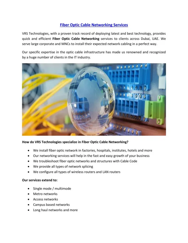
Fiber Optic Communication Overview, Cable Construction, Laying & Splicing. By OFC faculty, ALTTC, GZB. CONTENTS. HISTORY ADVANTAGES APPLICATIONS FIBER OPTIC PRINCIPLE WINDOWS OF OPERATION FIBER CLASSIFICATION FIBER PROPERTIES STANDARD FIBER TYPES A TYPICAL OPTICAL FIBER LINK

E N D
Fiber Optic Communication Overview, Cable Construction, Laying & Splicing By OFC faculty, ALTTC, GZB.
CONTENTS • HISTORY • ADVANTAGES • APPLICATIONS • FIBER OPTIC PRINCIPLE • WINDOWS OF OPERATION • FIBER CLASSIFICATION • FIBER PROPERTIES • STANDARD FIBER TYPES • A TYPICAL OPTICAL FIBER LINK • CURRENT TRENDS IN FIBER OPTIC COMMUNICATION OFC Faculty Optical Fiber Communication
“HISTORICAL PERSEPECTIVE”(1) • 1790: Optical telegraph was devised by Claude Chappe. • 1880: Alexander Grahem Bell invented the PHOTOPHONE. • 1940’s: Optical guides with reflective coating to carry visible light. • 1960:Invention of “LASER”-The first major break through in fiber optic technology. Unguided (non fiber) communication systems were developed after laser discovery. • 1966 Onwards: Developmentof optical fibers by companies like Corning Glass (very high loss). • IN 1970, Low loss fiber was developed and OFC system became practical. It was operated at wave-length around 820 nm and at attenuation of 1db/km. • Now fibers with losses of only a fraction of 1 db/km are available (0.15-0.35 db/km). OFC Faculty Optical Fiber Communication
“HISTORICAL PERSEPECTIVE”(2) OFC Faculty Optical Fiber Communication
ADVANTAGES OF FIBRE COMMUNICATIONS (1) • High information carrying capacity: A valid comparison would be on the basis of cost per meter per telephone channel, rather than just cost per meter. • Resource plentiful: The basic materials are either silicon dioxide for glass fibers or transparent plastic which are plentiful • Less attenuation: A typical fibre attenuation is 0.3 dB/km. Whereas a coaxial cable (RG-19/U) will attenuate a 100-Mz signal by 22.6 dB/km. • Greater safety: Optic fibers glass/plastic, are insulators. No electric current flows through them. OFC Faculty Optical Fiber Communication
ADVANTAGES OF FIBRE COMMUNICATIONS(2) • Immunity to Radio Frequency Interference: Fibers have excellent rejection of radio-frequency interference (RFI) caused by radio and television stations, radar, and other electronics equipment. • Immunity to Electromagnetic Interference: Fibers have excellent rejection of electromagnetic interference (EMI caused by natural phenomena such as lighting, sparking, etc). • No cross-talk: The optic wave within the fiber is trapped and does not leaks out during transmission to interfere with signals in other fibers. • Higher Security: fibers offer higher degree of security and privacy. OFC Faculty Optical Fiber Communication
ADVANTAGES OF FIBRE COMMUNICATIONS (3) • Small size and light weight: typical optical cable has a fiber dia. of 125m, cable dia. 2.5 mm and weight of 6 kg/km in comparison a coaxial cable (RG-19/U) has a outer dia. Of 28.4 mm, and weight 1110 kg/km. • Corrosion : Corrosion caused by water/chemicals is less severe for glass than for copper. • Less temperature sensitive: Glass fibers can with stand extreme temperatures before deteriorating. Temperatures up to 800 C leave glass fiber unaffected. OFC Faculty Optical Fiber Communication
APPLICATION OF FIBER OPTIC COMMUNICATIONS • Telecommunications: Long-Distance Telecommunications. Inter-exchange junction. Fibre in the loop (FITL). • Video Transmission: Television broadcast, cable television (CATV), remote monitoring, etc. • Broadband Services: provisioning of broadband services, such as video request service, home study courses, medical facilities, train timetables, etc. • High EMI areas: Can be laid along railway track, through power substations and can be suspended directly from power line towers, or poles. • Military applications: • Non-communication fiber optic: eg. fiber sensors. OFC Faculty Optical Fiber Communication
Optic review Ray Theory: • A number of optic phenomena are adequately explained by considering light as narrow rays. • The theory based on this approach is called geometrical optics. • These rays obey a few simple rules: 1. In a vacuum, rays travel at a velocity of c =3x10⁸m/s. In any other medium, rays travel at a slower speed, given by v = c/n n =refractive index of the medium. 2. Rays travel straight paths, unless deflected by some change in medium. 3. If any power crosses the boundary, the transmitted ray direction is given by Snell’s law: n1 sin Øi = n2 sin Ør OFC Faculty Optical Fiber Communication
PRINCIPAL OF TOTAL INTERNAL REFLECTION n1 = 1.48 n2 = 1.46 1 REFLECTED RAYS INCIDENT RAYS 1 2 ¢i 3 n1 3 2 ¢r 1 n2 REFRACTED RAYS OFC Faculty Optical Fiber Communication
Core THE OPTICAL FIBRE Refractive index 6-10 m 125 m Cladding OFC Faculty Optical Fiber Communication
LIGHT PROPAGATION IN FIBRE OFC Faculty Optical Fiber Communication
LIGHT PROPAGATION IN FIBRE OFC Faculty Optical Fiber Communication
LIGHT PROPAGATION IN FIBRE 1 2 3 3 2 1 OFC Faculty Optical Fiber Communication
LIGHT PROPAGATION IN FIBRE 1 2 3 3 2 1 OFC Faculty Optical Fiber Communication
INDEX OF REFRACTION MATERIALS Air 1.0 Carbon dioxide 1.0 Water 1.33 Ethyl alcohol 1.36 Magnesium fluoride 1.38 Fused silica 1.46 Polymethyl methacrylate polymer 1.5 Glass 1.54 Sodium chloride 1.59 Zinc sulfide 2.3 Gallium arsenide 3.35 Silicon 3.5 Indium gallium arsenide phoshide 3.51 Aluminium gallium arsenide 3.6 Germanium 4.0 OFC Faculty Optical Fiber Communication
NATURE OF LIGHT Wave Nature of Light : • Many light phenomena can be explained by realizing that light is an electromagnetic wave having a very high oscillation frequencies. • The wavelength of light beam: = v/f v = beam velocity f = its frequency. Particle Nature of light : • Sometimes light behaves as though it is made up of very small particles called photons. The energy of a single photon is: Wp = hf joules h = 6.626 x 10⁻³⁴ j x s is Planck’s constant.. f = frequency. OFC Faculty Optical Fiber Communication
ELECTROMAGNETIC SPECTRUM 1015 1014 1013 1012 1011 1010 109 108 107 106 105 104 103 102 101 ULTRAVIOLET INFRARED Visible wavelengths 0.4 m (red) • Silica glass fiber attenuates light heavily in visible & UV regions. • Glass fiber is relatively efficient in infrared region. • Three window of operation are at 0.85, 1.3 and 1.55 m. MICROWAVE RADIO POWER OFC Faculty Optical Fiber Communication
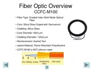
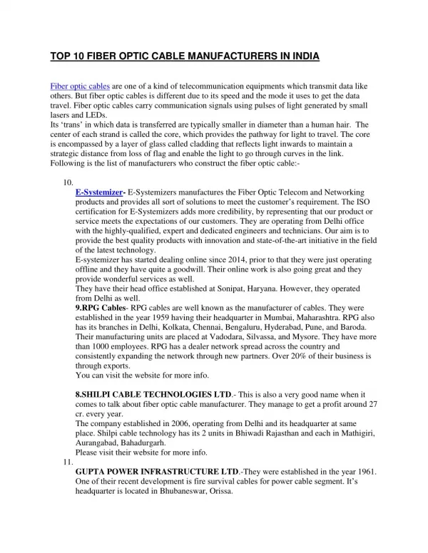
CONSTRUCTION OF OPTICAL FIBER CABLE Basic Fibre • core with R.I., n1 is supported by concentric cladding layer with R.I. n2. • R.I. of core is greater than cladding (n1 > n2). • The cladding layer is surrounded by one or more protective coating. • Change in RI is achieved by selectively doping the glass perform. CORE CLADDING OFC Faculty Optical Fiber Communication
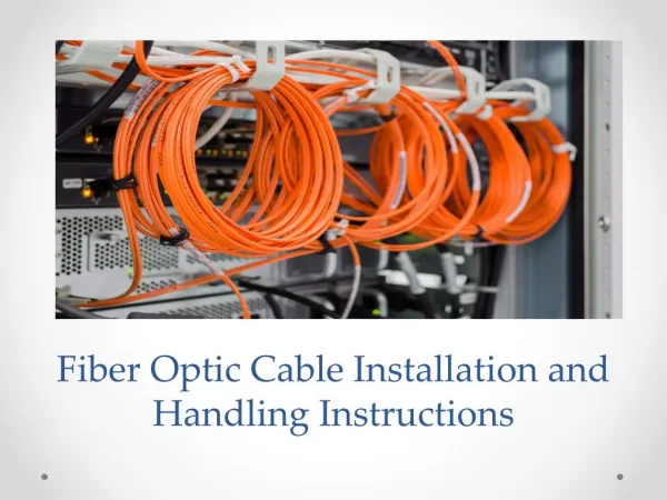
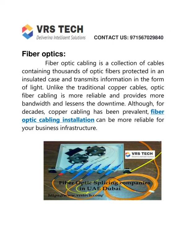
CABLING OF OPTICAL FIBRE • Cabling is done to protect the fiber during transportation, installation & operation. • Cabling protects the optical fibers from mechanical damage and environmental degradation. • It resembles conventional metal cables externally. • There are a variety of cable design available and irrespective of their design ,fiber optic cables have the following parts in common : • Buffer : to protect fiber from outside stress; materials used - nylon, or plastic. • Strength member : to reduce stress due to pulling, shearing, and bending; materials used-textile fibers (kevlar), or steel. • Cable filling compound: to prevent moisture intrusion and migration in the cable. • Cable jacket : to protect the fiber against cut and abrasion; material used-polyethylene polyurethane, polyvinyl chloride or teflon. OFC Faculty Optical Fiber Communication
CLASSIFICATION OF OPTICALFIBRE Material Classification : • Liquid core fibre. • All fused-silica-glass fibre: have silica-core and silica-cladding. • Plastic-clad-silica (PCS) fibre: have silica core and plastic cladding. • All-plastic fibre : have both core and cladding made up of plastic. • Compound glass fibre such as fluride glass fibre. Modal classification : • Similar to metallic wave guides, there are stable propagation states of electromagnetic waves in an optical fibre called modes. • Fibers can be classified based on number of modes available for propagation : Single-mode (SM) fibre Multi-mode (MM) fibre. Classification based on refractive index profile : • Step index (SI) fibre. • Graded index (GRIN) fibre. OFC Faculty Optical Fiber Communication
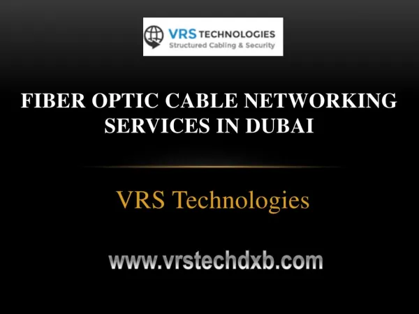
2a 2a 2a CLASSIFICATION OF OPTICAL FIBRE 8 - 12 m a) Single mode step-index fiber 50 - 200m b) Multi mode step-index fiber 50 m C) Multi mode GRIN fiber OFC Faculty Optical Fiber Communication
WINDOW CONCEPT IN SPECTRUM OF OPTICAL FIBER - 190 THz - 50 THz Cut - off wave length for single - mode fibre 0 1 2 3 4 5 OH- OH- Attention (db/km) OH- Wavelength (m.) 0.7 0.8 0.9 1.0 1.1 1.2 1.3 1.4 1.5 1.6 1.7 First Window Fourth Window Second Window Third Window OFC Faculty Optical Fiber Communication
LAYING OF CABLE soil categorization : ( for depth of trench ) (A) Rocky : Cable trench, where it is not possible to be dug without blasting and/or chiseling. (B) Non Rocky : Other than ‘A’ above, soil mixed with stone and soft rock. Pipes for cable laying Advantage for using pipes :1.It gives mechanical protection 2.Pipes can be laid in advance so that the cable laying is faster (1) HDPE pipe 75 mm (diameter) length 5m. (approx 18 to 20’ ) (2) HDPE pipe 50 mm (diameter) length 5m. (approx 18 to 20’ ) (3) PLP pipe (40 mm. outer diameter ) length 1km/200m OFC Faculty Optical Fiber Communication
LAYING OF CABLE • Mow manual laying method is discouraged as it is expensive , time consuming and also due to safety consideration. • Now for digging JCB machines are preferred. • Air blowing method by using Pressure machine is used for cable laying. OFC Faculty Optical Fiber Communication
LAYING OF CABLE Measurement of cable depth Depth should be measured from the top of pipe. However it is acceptable, if it is less upto eight cms from the specified depth. • Cross country rout (normal soil): HDPE pipe or PLP pipe depth is 1.5 meter . In rocky area minimum depth 0.9 m ( where digging more then 1 meter above pipe is not possible due to any Obstruction etc) should be considered. However, all cables having depth less then 1.2 meter should be protected by RCC/GI pipes OFC Faculty Optical Fiber Communication
(B) In built up area (city/town/urban area): (1) OF cable should be laid through exiting duct. (2) GI pipe or RCC pipe at the entry of duct. (3) In non duct area it should be laid through HDPE pipe/PLP pipe at depth of 1.5 meter using RCC/GI pipe for protection. (4) Depth in rocky soil may be consider as 0.9 to 1.0 meter (C) On culvert/bridge over river and nallah: (1) At the depth of 1.5 meter. Pipe length should be extended upto 2 meters at both ends. (2) This should be fixed along the parapet wall/bridge wall when river or nalla is full of water through out year, through fixed GI pipe on wall at suitable height above the water level. OFC Faculty Optical Fiber Communication
(D) Along rail bridge or crossing : Through HDPE pipe/PLP pipe protected by RCC or iron pipe as per the prescribed by railway authority. • On road crossing : At a depth of 1.5 meter through HDP pipe enclosed in RCC pipe extended by 3.0 meter to the either side end of the road. Indicators along route : (A) Route indicator At every 200 m route length, showing name of route & no of indicators. (B) Joint indicator : At every joint (Splice), generally it is placed at every 2/4 Km(Drum length) (C) Branch (Root diversion) indicator: Provided at route diversion or branching from the main root. OFC Faculty Optical Fiber Communication
LOSSES IN OPTICAL FIBER • There are several points in an optic system where losses occur. • These are: coupler, splices, connectors and the fiber itself. • Losses associated within the fiber classified as under: • Losses due to absorption:Even the purest glass will absorb heavily within specific wavelength regions. Other major source of loss is impurities like, metal ions and OH ions. • Losses due to scattering: caused due to localized variations in density, called Rayleigh scattering and the loss is: L = 1.7(0.85/)4 dB/km is in micrometers • Losses due to geometric effect: • micro-bending. • macro-bending. OFC Faculty Optical Fiber Communication
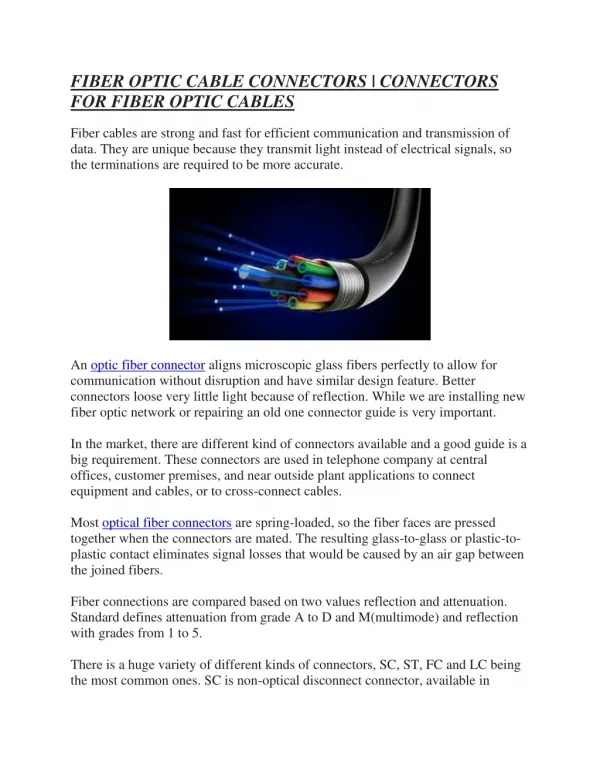
GENERAL ANALYSIS OF OTDR PLOT • OTDR is used for measurement of splice loss/ fiber loss in a section. • Optical power meter is used to know total loss of terminated cable section. FRESNE REFLECTIONS LOSS (db) SPLICE CONNECTOR DISTANCE (KM) OFC Faculty Optical Fiber Communication
DISPERSION IN FIBER • Dispersion is spreading of the optical pulse as it travels down the length. • Dispersion limits the information carrying capacity of fibre. • Classified as : Material Disp, Waveguide Disp. & Modal Disp., • Material Dispersion: • R.I. varies with Wave length causing velocity variation. d n2 z • Pulse spread : (t/L) = - C d2 = - M • Waveguide Dispersion: • effective R.I. varies with wavelength for given film thickness (n eff = c/vg) d n2 eff z • Pulse spread : (t/L) = - C d2 = - M g • Modal Dispersion: • pulse spreading caused by various modes. • Pulse spread:(t/L) = Ln1 2 /2c for GRIN fiber • Total Dispersion = - (M + Mg ) L for SM fiber • = (modal disp.)2 + (mat. disp.)2 for MM fiber (as MG = 0). OFC Faculty Optical Fiber Communication
TRANSMITTER MEDIUM RECIEVER Ligh t source Ligh t sansor ELECTRICAL SIGNAL BASIC FIBRE OPTIC COMMUNICATIONS A basic comm. System consists of : a transmitter, a receiver, & a medium. • Optical Transmitters: • convert electrical signals to optical. • Optical Receivers: • convert optical signal to electrical. • The basic elements in transmitters: Electronic interfaces, Electronics processing circuitry, Drive circuitry, light source, optical interfaces, output sensing and stabilization, Temperature sensing and control. • The basic elements in an optical receiver: Detector, Amplifier, Decision circuits. ELECTRICAL SIGNAL OFC Faculty Optical Fiber Communication
OPTICAL SOURCES • The device which actually converts electrical signals to its optical equipment. • Most common light sources: • light-emitting diodes (LEDs) . • Light Amplification by Stimulated Emission of Radiation (laser) diodes. • It is particularly required in lasers to maintain stable output power by way of feedback mechanism. • Laser is very sensitive to temperature. Operating characteristics of a semiconductor laser - notably threshold, current, output power, and wavelength change with temperature. Hence temperature sensing and control is required to maintain stable temperature. OFC Faculty Optical Fiber Communication
DETECTORS • The detectors used in fibre optic communications are semiconductor photodiodes or photodetectors. • It converts the received optical signal into electrical form. • Pin photodiode: cheaper, less temperature sensitive, and requires lower reverse bias voltage. • Aavalanche photodiode (APD): used where receiver is to detect lower power, OFC Faculty Optical Fiber Communication
SYSTEM DESIGN • Power budget: for a link to be feasible. Source Transmitting Power - (coupling Loss to fibre + Connectors Losses + Fibre Loss + Splicing Loss Maintenance Margin) Receiver Sensitivity • Rise time Budget: to check total link rise i.e. this time is to be within permissible limit. OFC Faculty Optical Fiber Communication
SYSTEM CONSIDERATIONS *NUMBER OF CIRCUITS * TRANSMISSION DISTANCE * UPGRADABILITY Detectors * Responsivity * Dark Current * Gain Sources * Wavelength * Line Width * Rise Time PIN APD Cable network * Route Loss * Route BW * Network Flexibility PIN APD LED LASER Fibre Network Fiber Loss Topology Bandwidth OFC Faculty Optical Fiber Communication
Thank You OFC Faculty Optical Fiber Communication