Download
1 / 24
240 likes | 258 Vues
Explore the fundamentals of electricity - from electrons and circuits to Ohm’s Law and multimeter usage. Learn about series and parallel circuits, Ohm’s Law equations, boat circuit issues, and magnetic fields. Discover how to measure voltage, current, and resistance, and master the principles that govern electrical power. Enhance your understanding with practical examples and insights into boat circuit problems, multimeters, and magnetic lines of force.

E N D
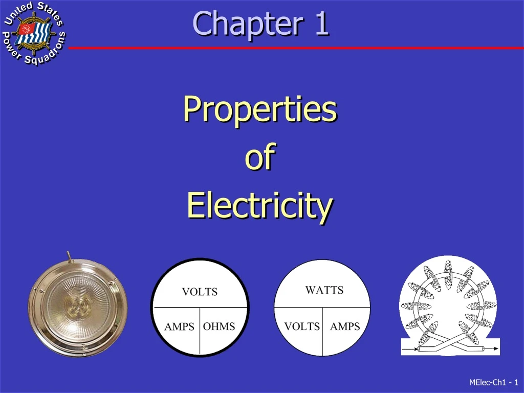
Chapter 1 Properties of Electricity
Overview • What is Electricity • Ohm’s Law • Boat Circuit Problems • Multimeters • Magnetic Lines of Force
What is Electricity • Electricity consists of electrons • Negatively charged • Electrons actually flow from negative to positive • Current “flow”, by convention, from positive to negative • Conductors have electrons that readily move • e.g. silver, copper, metal and liquids (salt water) • Insulation has tightly bonded electrons • Charges do NOT move • e.g. plastic, rubber, glass and ceramics
Water Analogy • Height of water = Voltage • Valve = Switch • Water wheel = Electric motor • Small pipe = Resistance
Electrical Circuits • Simple Series Circuit • Same current flow through all devices
Complex Series Circuit • If one light bulb burns out… • No lights will be on • Therefore, not used for light circuits Off Off
Complex Parallel Circuit • If one light bulb burns out… • Other will remain on • Therefore, used for light circuits On On
Ohm’s Law • E = Voltage (pressure) in volts • I = Current (rate of flow) in amperes • R = Resistance (friction) in ohms • P = Power (work) in watts E = I * R R = E / I I = E / R P = I * E P = I2* R P = E2 / R E I R
Practice (fig 1-5) • Given 12 volts and 4 amps • What is resistance? E = I * R R = E / I R = 12 / 4 R = 3 ohms (or 3 Ω) 12 VDC 4.0 Amps
Practice (fig 1-6) RT = R1 + R2 • Given 12 volts and 8 ohms • What is current? E = I * R I = E / R I = 12 / 8 I = 1.5 amps 4 ohms (each) 12 VDC
2 Ohms 6 Ohms 6 Ohms Practice (fig 1-8) • What is current in each device? 6 amps in 2 ohms 2 amps in 6 ohms (each) • What is total current? IT = I1 + I2 + I2 IT = 10 amps 12 VDC
Electrical Power • Watt is unit of electrical power • Given 12 VDC and total resistance of 6 Ω • What is total power? I = E / R I = 12 / 6 I = 2 amps P = E * I P = 12 * 2 P = 24 watts
What We Have Learned So Far • Electricity is the negatively charged electrons that have been freed from the structure of an atom • For electricity to perform some useful function it must flow in a circuit • There are two basic types of electrical circuits • The Series Circuit • The Parallel Circuit • Using Ohm's Law we can calculate the three electrical values in a circuit, i.e. Voltage, Amperage, and Resistance • The fourth electrical value is Power • Power is measured in Watts • Using the PIE equation we can calculate Power • Using Ohm's Law and PIE equation if we know any two values we can find the other two
Boat Circuit Problems • Open Circuit is “break” in electrical wiring • Current flow (path) is interrupted • Sometimes deliberately by switch • Short circuit is electrical wiring shortened from original length • Shorts to ground • Interwiring short • Internal short
Multimeters • Used to measure • Voltage • Current • Resistance • Types of Multimeters • Analog • Digital • Preferred • Easier to read
Measuring Voltage • Voltage to DC • Range to 20 volts • Red lead to positive • Black lead to negative • Meter across load • Parallel with load • Battery voltage is 12.6
Measuring Voltage at Light • with good fuse • and switch “On” • Should measure approx. 12 VDC at each light
Measuring Voltage Drop • Across a closed switch • Should measure zero volts • Across a high resistance “connection” • Should measure a voltage drop
Measuring Current • Current to DC • Range to 10 amps • Red lead to current jack on multimeter • Insert meter in series with circuit When measuring voltage - meter is across the load
Measuring Resistance • Function to resistance • Touch test leads together • Adjust resistance to zero (0.0) ohms • Place test leads across device to be measured • Continuity measurement • When test leads are across low resistance (Good circuit or device) • Will hear a buzz indicating continuity
Magnetic Lines of Force • Results of Electrical Current • Heat (due to resistance in wire) • Chemical reaction (in current carrying solution) • Magnetic Field (illustrated)
AWG#2 (Large Wire) AWG#16 (Small Wire) Remote Control Circuit Small current through solenoid coil - Controls larger current, through contacts, to Starter Motor
Summary • Electricity is negatively charged electrons • Current flows from positive to negative • Types of circuits • Series (one path for current flow) • Parallel (multiple paths for current flow) • Ohm’s Law • E = I * R • P = E * I • Boat Circuit Problems • Open Circuits • Short Circuits
Summary - 2 • Multimeter • Digital preferred • Measure voltage across (parallel to) load • Can also measure voltage drop • Measure current in series with load • Magnetic Lines of Force • Concentrated in coil • Solenoids use in remote control circuits • Small current controls large current