Download
1 / 31
310 likes | 473 Vues
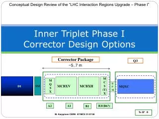
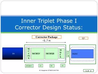
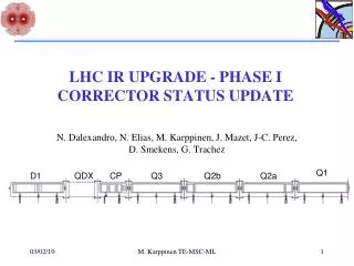
N. Dalexandro, N. Elias, M. Karppinen, J. Mazet, J-C. Perez, D. Smekens, G. Trachez. Q1. D1. QDX. CP. Q3. Q2b. Q2a. LHC IR UPGRADE - PHASE I CORRECTOR STATUS UPDATE. Corrector Package (CP). MCXSO MCXO. MCXSSMCXS. IP. MCXT. MQXS. MCXBV. MCXH. ~0.5 m. ~0.5 m. ~0.5 m. ~0.9 m.

E N D
N. Dalexandro, N. Elias, M. Karppinen, J. Mazet, J-C. Perez, D. Smekens, G. Trachez Q1 D1 QDX CP Q3 Q2b Q2a LHC IR UPGRADE - PHASE ICORRECTOR STATUS UPDATE M. Karppinen TE-MSC-ML
Corrector Package (CP) MCXSO MCXO MCXSSMCXS IP MCXT MQXS MCXBV MCXH ~0.5 m ~0.5 m ~0.5 m ~0.9 m ~1 m ~1 m M. Karppinen TE-MSC-ML
Correctors in Q2 Q3 Q2b Q2a Q1 • Base-line (HV and VH) orbit corrector scheme allows controlling the orbit to a level 3 times larger that then BPM resolution. • To reach the same level as the effective BPM resolution : • Provide 1.5 Tm (1.8 Tm) in H&V-plane in BOTH locations. • Feasibility study underway on combined H/V-corrector that meets the reliability requirements (Report by Mid-2010 + Model work..) • An extra H/V pair means: • Magnet R&D, material R&D, design, component & tooling procurement • Additional powering and protections circuits MQXC MCXBV (MCXBHV?) MCXBH (MCXBHV?) MQXC MQXC MQXC 10 m 1..1.3 m 7 m 7 m 1..1.3 m 10 m REF: S. Fartoukh, R. Tomas, J. Miles: “Specification of the Closed Orbit Corrector magnets for the NEW Inner Triplets”, sLHC Project Report 030 M. Karppinen TE-MSC-ML
Radiation Environment (Q2a & CP) Courtesy of F. Cerrutti & A. Mereghetti EN-STI-EET, FLUKA-team M. Karppinen TE-MSC-ML
Radiation Environment (sLHC v2.0) • Luminosity: 2 L0 = 2 ×1034cm-2 s-1 & 1000 fb-1 • Peak dose CP: • ~50..65 MGy ø120 mm aperture, no shielding • ~30..35 MGy ø140 mm aperture, no shielding • ~10 MGy ø140 mm aperture, 10 mm SS • Peak dose in Q2 (with 13 mm liner in Q1): • ~28 MGy, ø120 mm aperture, no shielding • ~ 8 MGy ø140 mm aperture, 10 mm SS Courtesy of F. Cerrutti & A. Mereghetti EN-STI-EET, FLUKA-team M. Karppinen TE-MSC-ML
Organization • MCXB • Design CERN • Model CERN • Series (20 off) Special French Contribution/CERN? • MQXS • Design CERN • Model & R&D CERN & STFC • Series (5 off) Special French Contribution/CERN? • MCXS and other Higher Order Correctors (TBC) • Design CIEMAT • Model CIEMAT • Series (5 off) Special French Contribution/CERN? • Testing (cold) • at CERN • Plan B for Models: RAL, CEA (TBC) • Cold mass integration and cryostat assembly at CERN M. Karppinen TE-MSC-ML
Organization: STFC Involvement • R&D on coated metallic end spacers for cosƟ coils (rad resistance, alternatively usable for thermal reaction of Nb3Sn Coils) • Validation of porous all polyimide insulation for the 18 strand Rutherford cable • Study of E-modulus of the insulated cable / dielectric properties • Assembly of the models at CERN (short mech. model & model) M. Karppinen TE-MSC-ML
NIT Funding Courtesy of S. Russenschuck M. Karppinen TE-MSC-ML
MCXB 4-Block Design 1000 Ø570 Ø140 Field strength 1.5 Tm Operating temp 1.9 K Current 2.4 kA Inductance 10 mH New 4.37 mm cable & Polyimide insulation Self-supporting collars Single piece yoke Courtesy of L. Favre M. Karppinen TE-MSC-ML
MCXB Initial 6-Block Design M. Karppinen TE-MSC-ML
MCXB Single-Layer Design M. Karppinen TE-MSC-ML
18-Strand Cable *) extracted strand March -09 Polyimide Insulation: 2 x 25µm + 55 µm Trial cabling length (~100 m) done! Insulation trials & characterization in progress.. M. Karppinen TE-MSC-ML
Cable Insulation M. Karppinen TE-MSC-ML
Cable insulation M. Karppinen TE-MSC-ML
Conductor and Insulation Needs ~250 km of strand in stock @CERN M. Karppinen TE-MSC-ML
MCXB 4-Block Design: FEA Courtesy of N. Elias 150 mm model to verify material properties and assembly parameters M. Karppinen TE-MSC-ML
MCXB 3D (return end) Design current = 2.4 kA Coil length = ˜0.84 m Total length = ˜1 m b3= -0.04 units b5= -13.48 units b7= -9.11 units b9= -2.14 units b11= -0.82 units ˜260 mm B1= 0.37 Tm x 2 + 2.28T x 0.34 m = 1.5 Tm ENDS STRAIGHT M. Karppinen TE-MSC-ML
MCXB 3D Harmonics Integrated Field (2.4 kA) B1 1.5 Tm b3 0.20 unit b5 -3.59 unit b7 -4.46 unit b9 -0.84 unit b11 -0.41 unit a1 -22.71 unit a3 6.32 unit a5 -0.52 unit a7 -0.07 unit a9 0.03 unit a11 -0.02 unit M. Karppinen TE-MSC-ML
MCXB 4-Block Design Quench (3kA) Rd = 0.16 Ω Warm diode No heaters M. Karppinen TE-MSC-ML
MQXS Assembly 900 Ø570 Ø140 New 4.37 mm cable & Polyimide insulation Single layer coils Self-supporting collars Single piece yoke Field strength 0.65 Tm Gradient 25.5 T/m Operating temp 1.9 K Current 2.4 kA Inductance 3.3 mH Courtesy of G. Villiger M. Karppinen TE-MSC-ML
MQSX Initial 2-Layer Design M. Karppinen TE-MSC-ML
MQSX Single-Layer Base-Line Design M. Karppinen TE-MSC-ML
MQSX 3D (return end) Design current = 2.4 kA Coil length = 0.7 m Total length = ~0.9 m a6= -0.39 units a10= 0.01 units a14= 1.35 units ˜120 mm A2(40 mm)= 0.087 Tm x 2 + 1.02 T/m x 0.47 m = 0.65Tm ENDS STRAIGHT M. Karppinen TE-MSC-ML
MQSX 3D harmonics Integrated Field (2.4 kA) A2 0.65 Tm a6 0.04 unit a10 0.25 unit a14 -1.37 unit b2 19.59 unit b6 0.49 unit b10 -0.08 unit b14 -0.01 unit M. Karppinen TE-MSC-ML
MQSX Single Layer Design Quench (3kA) Rd = 0.16 Ω Warm diode No heaters M. Karppinen TE-MSC-ML
MQXS Single-Layer Design: FEA Courtesy of N. Elias M. Karppinen TE-MSC-ML
Super-ferric MCSX • Design report in progress • This concept is no longer compatible with the requirements • Updated scope of CIEMAT’s involvement being discussed Courtesy of Iker Rodriguez (CIEMAT) M. Karppinen TE-MSC-ML
Next steps… • Optics studies => Confirm parameters & Lay-out (getting there..) • Cabling & insulation trials and characterization (in progress..) • Detailed fabrication design (magnet & tooling) (in progress..) • Model magnet construction (MCXB, MQXS) • Feasibility study of combined H-V orbit corrector (in progress..) • Material R&D, Trials, Magnet model..? • Higher order correctors • Magnetic and mechanical designs (Feb -10 .. Sep -10) • Material R&D (Mar -10 .. Nov -10) • Conductor procurement (Aug -10 .. Jul -11) • Model/prototype magnets construction (Jul -11..May -12) M. Karppinen TE-MSC-ML
Milestones… (MCXB & MQXS) • Parameter list Oct-09..Jan-10 • Magnetic and mechanical design Nov-09 • Fabrication drawings May-10 • Trial coils Jul-10 • Mechanical model May-10 & Jul -10 • Model magnets completed Dec-10 • Technical specifications Mar-11 • Industrial contracts Jul-11 • Pre-series magnets Jul-12 • Series production Sep-12 .. Dec-13 M. Karppinen TE-MSC-ML
Preliminary Cost-estimate Low Profile Costing, considering free material (SC cable, steel for collars, iron for laminations), and Contractors already equipped with curing press and collaring press. M. Karppinen TE-MSC-ML
Yet To Define… • Integration & Parameters • Final optics, Orbit correction scheme, error tables • Bus-bar routing and X-sections • Cold-mass & Cryo-magnet integration • QPS design and lay-out • Contractual • Scope of Special French contribution • Industrial procurement and/or in-house production • Testing • Funding.. M. Karppinen TE-MSC-ML