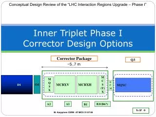
Inner Triplet Phase I Corrector Design Options
360 likes | 502 Vues
This document presents an overview of the design options for the Inner Triplet Phase I Corrector Package Q3 of the LHC Interaction Regions Upgrade. It discusses the requirements, constraints, and current design status of different correctors, including MCBX, MQSX, and MCSX. Key aspects related to fabrication, such as coil winding techniques and quench protection, are also covered. This review emphasizes the challenges posed by a hostile environment and the need for reliable systems to meet operational demands.

Inner Triplet Phase I Corrector Design Options
E N D
Presentation Transcript
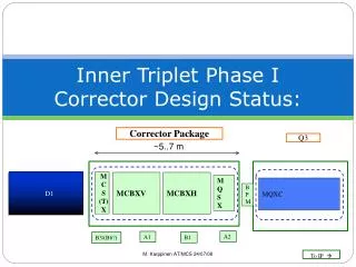
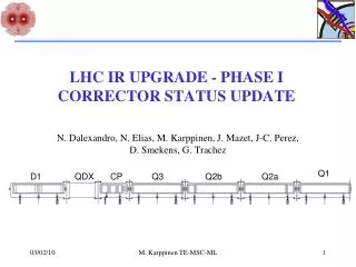
Conceptual Design Review of the “LHC Interaction Regions Upgrade – Phase I” Inner Triplet Phase I Corrector Design Options Corrector Package Q3 ~5..7 m SM M C S (T) X D1 MCBXV MCBXH M Q S X MQXC B PM A2 A1 B3/(B6?) B1 To IP M. Karppinen CERN AT/MCS 31/07/08
Acknowledgements: • STFC/RAL: E. Baynham, S. Canfer, P. Loveridge, J. Rochford • CIEMAT: F. Toral, I. Rodriguez • CERN: B. Auchmann, F. Cerrutti, G.-J. Coelingh, N. Elias, S. Fartoukh, S. Russenchsuck, N. Schwerg, T. Sahner, E. Wildner, M. Karppinen CERN AT/MCS
Outline • Corrector requirements and constraints • Some LHC corrector specific fabrication aspects • Design status: • MCBX (CERN) • MQSX (STFC/RAL & CERN) • MCSX (CIEMAT & CERN) • Summary M. Karppinen CERN AT/MCS
Requirements & Constraints • Fit all correctors in dedicated cryo-assembly within 5..7 m between Q3 and D1 • Aperture ≥ø120 mm (TBC) • Operating temperature 1.9 K • (Try to) Use existing: • Power converter • Bus-bars • Current leads • Quench detection & protection systems M. Karppinen CERN AT/MCS
Requirements.. (cont) • MCBX • correct for a triplet misalignment of 1mm • 1-1.5 Tm for generation of X-angle, parallel separation, and transverse adjustment of the IP • 6 Tm in H- and V-plane (presently 3 x 1.51/1.56 Tm) • MQSX • Compensate for triplet roll of 4 mrad • 20 Tm/m or 40 T/m x 0.5 m • MCSX • correct for b3 of D1 (29 Tm) • ~25 T/m2x 0.5 m (b3 = 6 units) • MCTX • MQX systematic b6 (1 unit) correction • MCSOX • Not yet clear, if required… Based on scaling the present triplets. New requirements not yet available M. Karppinen CERN AT/MCS
Requirements.. (cont) • Very hostile environment • Material selection (insulation, head spacers etc..) • Spare policy • “Intervention friendly” design of cryo-magnets • Radioprotection • Reliability: • MCBX must work, no redundancy • Cost • Investment on powering/cooling • Fabrication cost & spares M. Karppinen CERN AT/MCS
LHC Corrector Fabrication Aspects • Flat cable • Purpose built machine to bond 2-25 enamel (PVA) insulated wires together • Tolerance +0.02/-0.01 mm, unit lengths up to 160 m • Wires are connected in series on connection plate • Coil winding • Dipole coils with standard winding machine • Counter-winding technique used for single winding block coils • All coils epoxy impregnated in vacuum or by wet-laying • Coil lengths up to 1.5 m • Assembly • Epoxy-glass around the coils by vacuum impregnation or pre-preg • Pre-stress from shrink-fitted Alu/St.steel cylinders • Off-center laminations M. Karppinen CERN AT/MCS
Nb47%Ti PVA insulation RRR >100 Filament diameter 6-7 micrometer. Limited quantity available for model magnets Superconducting wire M. Karppinen CERN AT/MCS
Coil winding Counter-winding (MQSX) Dipole winding (MCBM) M. Karppinen CERN AT/MCS
Coil assembly M. Karppinen CERN AT/MCS
Present MCBX: Coil Fabrication M. Karppinen CERN AT/MCS
Present MCBX: Assembly M. Karppinen CERN AT/MCS
MCBX: Electrical Connections M. Karppinen CERN AT/MCS
MCBX for Phase I • From 3 nested to 2 separate H/V-steering magnets • Central field: 3 T => ~3.5 T • Total length: 0.7 m => ~2 m/unit • Aperture: ø90 mm => ø120 mm • Stored energy: 44kJ => ≥150 kJ • Field quality < 1unit @30 mm • Quench protection: none => active protection • Mechanical structure based on collared coils • First design iteration for Inom ≤600 A • Alternative high current designs based on MQY and MB cables M. Karppinen CERN AT/MCS
600 A Design wp = ~60 % on the LL 8-way cable PVA insulated wire Potted coils Each coil consists of 8 electrical circuits in series with a quench stopper in between Quench stopper between the coils Existing power converters Std. LHC QP system M. Karppinen CERN AT/MCS
MCBX: 600 A Design M. Karppinen CERN AT/MCS
MCBX: Quench analysis • Four 600 A cases analyzed at this point • Wire #4, 1.9 K, no dump resistor • Wire #4, 1.9 K, with dump resistor • Wire #4, 4.5 K, with dump resistor • Wire #3, 1.9 K, with dump resistor Additional cases to look into • Cable versions, with heaters/dump resistor • Include energy deposition from FLUKA M. Karppinen CERN AT/MCS
LHC 600 A circuit Courtesy of Gert-Jan Coelingh (AT-MEI) Design for Rd=0.7 Ω with 2 x mass available Ugnd ≤ 420 V Present Rd tested with 113 kJ (+115°C) Breaker designed for 750 A 3 spare systems available M. Karppinen CERN AT/MCS
Wire#4, 1.9 K, with Rdump Rd = 0.7 Ω (14.6 ms) Tmax = 140 K Ugnd = 400 V UR= 1100 V =>SAFE Tmax Quench origin M. Karppinen CERN AT/MCS
Wire#4, 1.9 K, with Rdump M. Karppinen CERN AT/MCS
Wire#4, 4.5 K, with Rdump Rd = 0.7 Ω (14.6 ms) Tmax = 110 K Ugnd = 350 V UR = 870 V =>SAFE Wire#3, 1,9 K, with Rdump Rd = 0.9 Ω (14.6 ms) Tmax= 250 K Ugnd = 1000 V UR = 3100 V =>RISKY M. Karppinen CERN AT/MCS
MCBX: Cable Design MB Outer Cable MQY Outer Cable x 2 Aperture easily enlarged (shielding) Much improved cooling (1.9K) Single or double layer coil (powering) Collars New power converters, cables, and leads. (Challenging around 0-current?) Active QPS (heaters/dump resistors) Can meet field quality requirements (yoke optim.) M. Karppinen CERN AT/MCS
MCBX: Cable variants MQY Outer Cable MQY Inner Cable MQY Inner Cable x 2 MQY Outer Cable x 2 M. Karppinen CERN AT/MCS
MCBX: Cable Design,1.9 K M. Karppinen CERN AT/MCS
Mechanical design: collars Courtesy of T. Sahner (TS-MME) Courtesy of N. Elias M. Karppinen CERN AT/MCS
MCBX Design status & plans • Magnetic design • X-sections for 600 A and Cable • Software development/testing • Quench analysis • 600 A versions • Cable design • FLUKA Studies • Design optimization • Mechanical design • Material selection • 2D&3D magnetic design • Model magnet (after Aug -09) • Model Test (after Sep -09) • Prototype Design & Construction (2010..) ✔ ✔ ✔ Next step Underway Underway M. Karppinen CERN AT/MCS
MCBX Summary • 600 A design based on wire #4 would allow re-using the existing powering and protection systems, but radiation & energy deposition may compromise the reliability • Cable design more robust, easier to make, makes full use of 1.9 K cooling, and offers more freedom for aperture size. Requires investment in powering and protection. • 1.9 K operation: • Extract the heat from energy deposition • More compact coils, shorter overall length • Savings in material and tooling cost • Reduced risk of fabrication failure (< 2 m, 600 A) • 1.9 K cooling is available • Decisions required (aperture, Inom, field quality) to start the detailed design and to meet the tight milestones for the project. M. Karppinen CERN AT/MCS
MQSX for Phase I • Gradient: 80 T/m => 40 T/m • Total length: 0.3 m => 0.8 m • Aperture: ø70 mm => ø120 mm • Stored energy: 4.2 kJ => ~10 kJ • Field quality < 1unit @30 mm • Quench protection: none => probably none (TBC) • Mechanical design based on the present concept • First design iteration for Inom <600 A based on wire #3 M. Karppinen CERN AT/MCS
MQSX: Present design M. Karppinen CERN AT/MCS
MQSX: Parameters M. Karppinen CERN AT/MCS
Field quality: First Estimate From S. Fartoukh • Scale measured mean MQXB to 30 mm • Scale with ß (12.5 km/4.5 km)n/2 • MQSX strength 0.004 of MQXB • To stay in the shadow allow <10 % M. Karppinen AT/MCS
Phase I MQSX M. Karppinen CERN AT/MCS
MQSX: Next steps • Moving forward with the baseline 6 wire 2 block configuration, there are a number of issues to be addressed. • Magnetically • Quench protection-should not be a problem, but needs to be confirmed • Effect of manufacturing tolerances on harmonic structure • 3d models: end effects, spacer optimisation • Mechanically • P. Loveridge has started looking at mechanical design issues and FEA • Radiation hard materials • Baseline definition • Key components • Preliminary drawings • Manufacturing costs Courtesy of James Rochford - STFC M. Karppinen CERN AT/MCS
MCSX for Phase I Courtesy of Fernando Toral (CIEMAT) M. Karppinen CERN AT/MCS
MCSX: Parameters (Draft 1) Courtesy of Fernando Toral (CIEMAT) M. Karppinen CERN AT/MCS
Summary • Verydemanding operating environment • MCBX shall have the same level of reliability as MQX (radiation hardness, cooling) • Cable design with active protection operating at 1.9 K is the most promising option • MQSX based on the present technology can meet the Phase I requirements • Super-ferric MCSX expected straight forward • Detailed design requires decision on aperture, operating current, and field quality targets M. Karppinen CERN AT/MCS