Download
1 / 9
170 likes | 378 Vues
Explore the application of torsional stress relays to detect and respond to high stress in turbine-generators, preventing damage and optimizing performance. Learn about the functions, features, and benefits of torsional relaying protection, including mitigation strategies for potential issues. This comprehensive guide explains how TSR technology safeguards machinery from various stressors, ensuring operational efficiency and reliability.

E N D
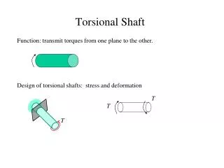
Application of Torsional Stress Relays GE Energy Dr. Daniel H. Baker March 12, 2010 g Imagination at work
The Difference Between “Mitigation” and “Protection” Protection Mitigation • Detects actual stress on the shaft itself, regardless of the cause • Responds to all causes of high stress, both known and unknown • Acts to prevent damage to the turbine-generator • SSR blocking filter or TCSC to reduce SSR caused by series capacitors • Series capacitor switching to avoid SSR • Auto transfer-trip to avoid certain operating conditions (HVDC terminal, series capacitors, steel mills) • Subsynchronous damping control (SSDC) on HVDC system Reduces Risk by avoiding Known Causes of high torsional stress Protects machine from All Causes of high torsional stress
Torsional Relaying Functions and Features • Measure instantaneous “stress” in limiting shaft for each torsional mode • Inverse time fatigue trip • Steady-state instability trip • Potential Primary and secondary trip circuits for • 1) tripping unit • 2) opening lines and/or bypassing series capacitors • Alarms to indicate when oscillations are present
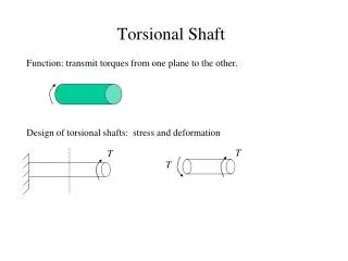
Typical Fatigue Curve for One Shaft Section • Shows shaft torque magnitude vs. cycles-to-failure (crack initiation) • Function of material properties and dimensions • Used to calculate loss-of-life and relay trip settings
TSR Protection Curve for One Torsional Mode Generator Trip Optional Line Trip
Example Application of TSR Protection – Worst Instability vs. Outages
Torsional Relaying Protection for SSR • No SSR problems for several contingencies (up to 3 in this example) • Possible Instability for multiple contingencies (5 or 6 in this example) • Torsional Relaying Protection Only is Adequate for this condition SSR problems with 2 contingencies or less would need Mitigation in addition to Protection