Download

1 / 48
600 likes | 1.34k Vues
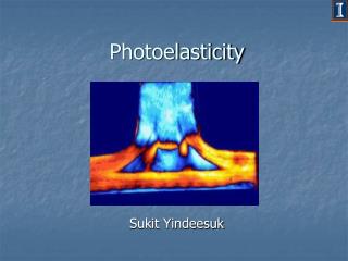
Fundamentals of Photoelasticity. Some Useful Definitions. How Stress Is Calculated. Principles of Photoelasticity. Stress Measurement Techniques. Strainoptic Technologies, Inc. Some Useful Definitions. Residual Stress Polarized Light Index of Refraction Photoelasticity

E N D
Fundamentals of Photoelasticity • Some Useful Definitions • How Stress Is Calculated • Principles of Photoelasticity • Stress Measurement Techniques Strainoptic Technologies, Inc.
Some Useful Definitions • Residual Stress • Polarized Light • Index of Refraction • Photoelasticity • Birefringence • Stress-Optical Constant • Retardation
Residual Stress Residual stress is an intrinsic tension or compression which exists in a material without an external load being applied. In glass, so-called permanent residual stress is induced in the primary manufacturing process. It is relieved through annealing or subsequently added in secondary thermal processing operations to impart desired mechanical characteristics.
Residual Stress When there is an equilibrium between the tensile and compressive stresses, the glass is said to be stable. An imbalance in residual stresses can cause unexpected weakness or spontaneous breakage.
Polarized Light • Light moves through transparent materials in the form of waves. The frequency of the waveform varies with the type of light. The standard wavelength for white light through glass is 565 nanometers (10-9 meters). • These waves are omnidirectional and “vibrate” out at a perpendicular angle from the direction (propagation) of the light beam. Propagation of light beam Light Source
Polarized Light When light passes through a polarizing lens, all components of the light wave are blocked except for the components of the light wave in the plane of vibration allowed to pass by the polarizing filter. Privileged Axis of Polarizer 1 Omnidirectional Vectors of Light Light Source
Polarized Light In “plane” or linear polarization, only the components of the light vector parallel to the privileged axis of the polarizer pass through. Light may also be subject to “circular” and “elliptical” polarization methods, which involve adding devices to the light path which alter its characteristics. Privileged Axis of Polarizer 1 Omnidirectional Vectors of Light Plane Polarized Light Light Source
Polarized Light If another polarizing filter is placed in the path of the polarized light beam, and rotated 90° (perpendicular) to the polarizing axis of the first filter, all light will be blocked. Privileged Axis of Polarizer 1 No Light (Dark Field) PrivilegedAxis of Polarizer 2 rotated 90 degrees to the polarizing axis of the first filter. Omnidirectional Vectors of Light Plane Polarized Light Light Source
Polarized Light If the second polarizing filter is rotated to an angle less than or greater than 90° relative to the first polarizing lens, only the components of the light wave vibrating in that plane will pass through the filter. Privileged Axis of Polarizer 2 <>90 Degrees Relative to Polarizer 1 Attenuated Light(Variable Field) Plane Polarized Light Light Source
Index of Refraction A material’s index of refraction is defined as the speed of light through a vacuum 3 x 10⁸ meters/sec divided by the speed of light through the material.
Photoelasticity The property exhibited by some transparent solids, whereby they become doubly refractive, or “birefringent,” when subjected to stress.
Birefringence When polarized light passes through a stressed material, the light separates into two wavefronts traveling at different velocities, each oriented parallel to a direction of principal stress (s1, s2) in the material, but perpendicular to each other. Reference Direction s1 Direction of Stress s2 Directionof Stress Point of Interest Light Source Plane Polarized Light
Birefringence Birefringence results in the stressed material having two different indices of refraction (n1, n2). In most materials, the index of refraction remains constant; however, in glass and plastics, the index value varies as a function of the stress applied. This gave rise to the Stress-Optic, or “Brewster’s” Law .
The Stress-Optic (Brewster’s) Law (n1 – n2) = CB (s1 –s2) WHERE n1,n2 = Indices of refraction CB = Stress-optical constant, in Brewsters s1, s2= Principal stresses
The Stress-Optic Law This law established that birefringence is directly proportional to the difference of principal stresses, which is equal to the difference between the two indices of refraction, n1-n2, exhibited by a stressed material. Therefore, birefringence can be calculated by determining Δn.
Retardation The phase difference between the two light vectors traveling through the material at different velocities (fast, slow) is known as retardation, commonly represented by the symbol delta, d. The retardation value divided by a material’s thickness is proportional to the difference between the two indices of refraction, i.e., d /t = Dn
Retardation Point of Interest Plane Polarized Light Retardation of Polarized Light Through a Stressed Material Reference Direction Light Source
The Stress Equation Retardation Thickness * Stress-Optical Constant Stress =
s = d/tCB WHERE s = Stress (in MPa*) d = Retardation (in nanometers) t = Thickness CB = Stress-optical constant (in Brewsters) *(1 MPa = 145 psi) The Stress Equation
Principles of Photoelasticity Instruments designed to observe objects under polarized light are called polariscopes or strain viewers. The first, or fixed, polarizing filter is known as the “polarizer.” The second, or rotating, polarizing filter is known as the “analyzer.” If the analyzer has a calibrated scale that can be used for making quantitative measurements, it is called a polarimeter.
Principles of Photoelasticity By rotating the second polarizing filter (analyzer), the user can control the amount (intensity) of light allowed to pass through. The components of the two light waves that do pass through at any given angle of analyzer rotation interfere with each other, resulting in a characteristic color spectrum. Retardation Analyzer Point of Interest Plane Polarized Light
Principles of Photoelasticity The intensity of colors displayed when a stressed transparent or translucent material is viewed under polarized light is modulated by the retardation.
Principles of Photoelasticity Each integer multiple of the standard wavelength of light (l = 565 nm for glass; 570 nm for plastics) is called a fringe (N).
Principles of Photoelasticity The intensity of the colors diminishes as the retardation or fringe order increases.
Principles of Photoelasticity Zero Order The photoelastic color sequence (showing increasing stress) is: Black (zero) Yellow Red Blue-Green Yellow Red Green Yellow Red Green Yellow Red First Order Second Order Third Order
Principles of Photoelasticity These color patterns, visible when using polarized light, can be used to observe and make a qualitative evaluation of stress in an object. This method is very subjective and requires experience and training.
Principles of Photoelasticity A quantitative measurement of residual stress can be obtained using a polarimeter, an instrument that measures retardation, which is proportional to stress.
Principles of Photoelasticity Plane Polarization and Circular Polarization
Principles of Photoelasticity To determine the direction of principal stresses in a sample, a plane polarization technique is typically used. To do this using plane-polarized light, it is important to first orient the sample such that the point of interest (POI) exhibits minimum light intensity.
Principles of Photoelasticity In this orientation, a direction of principal stress at the point of interest (either x or y) will be parallel to the axes of the analyzer and polarizer.
Principles of Photoelasticity Rotating the sample 45 degrees places the sample in the proper position for measuring retardation.
Principles of Photoelasticity Using circularly polarized light, the measurement is independent of the direction of the principal stresses at the point of interest. To change a plane polarimeter to a circular polarimeter, two ¼-wave platesare added to the light path as shown below. Axis of Polarization (Plane Polarizer) First 1/4-Wave Plate Added Retardation (d) Axis of Polarization(Analyzer) Point of Interest Second1/4-Wave Plate Added Retardation (d)
Principles of Photoelasticity The relation used for calculating the retardation of polarized light transmitted through a stressed material is: d = CBt (sx – sy) WHERE d =Retardation (in nanometers) CB = Brewster Constant t = Material Thickness sx,y = Principal Stresses
Observation of Color Pattern Method Measuring Techniques • Compensator Method • Analyzer Rotation Method
Observation of Color Pattern Method Strain Viewer/Polariscope
Observation of Color Pattern Method White light produces a complete spectrum of light. This includes the visible spectrum of 400 nm to 700 nm.
Observation of Color Pattern Method The intensity of the light is modulated by the retardation exhibited by the sample.
Results are highly subjective to interpretation Observation of Color Pattern Method • Can only be used for qualitative measurements
Compensator Method Compensator
Simplest method of measuring retardation Compensator Method • Compensator (wedge) is a calibrated, handheld device that optically adds a retardation of equal, but opposite sign to the sample. • The net result is a light intensity of zero, which is easily recognized visually as black in the color pattern.
There are two types of compensators in common usage: • Babinet or “Wedge” compensator (scale readout) Compensator Method • Babinet-Soleil or “Double-Wedge” compensator (digital readout)
Analyzer Rotation Method Analyzer Polarimeter (with microscope option)
The Analyzer Rotation Method uses a circular polarimeter setup as shown below. This is called the”Tardy” method. When only one ¼-wave plate is used, it is called the “Senarmont“ method. Analyzer Rotation Method Axis of Polarization (Plane Polarizer) First 1/4-Wave Plate Added Retardation (d) Axis of Polarization(Analyzer) Second1/4-Wave Plate Point of Interest Added Retardation (d)
The analyzer rotation method is generally used to measure fractional levels of retardation (<570 nm). Analyzer Rotation Method • The sample is first positioned parallel to the reference axis of the polarizer and analyzer. • The analyzer is rotated until a minimum light intensity is observed. • The sample is then rotated 45 degrees from the reference axis.
Retardation is calculated from the fractional fringe order that is read directly from the dial. Analyzer Rotation Method 509 nm = 0.9 x 565
This measurement (509 nm of retardation) is then converted to stress using the equation below or referring to a conversion chart. Analyzer Rotation Method s = d/tCB WHERE s =Stress (in MPa) d = Retardation (in nanometers) t = Thickness CB = Brewster Constant (1 MPa = 145 psi)
Example: Retardation (d) = 509 nm Thickness (t) = 6 mm CB = 2.54 Analyzer Rotation Method s = d/tCB =509/(6.0 x 2.54) • = 509/15.24 • = 33.4 MPa or 4843 psi