Transmission Media
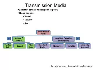
Transmission media are the physical paths through which messages travel from sender to receiver, essential in computing and telecommunications. They include guided media like twisted-pair, coaxial, and fiber-optic cables, and unguided media that transmit signals wirelessly through electromagnetic waves. This overview delves into the characteristics of various transmission media, covering their construction, advantages, common applications, and the electromagnetic spectrum they utilize for effective data and voice communication.


Transmission Media
E N D
Presentation Transcript
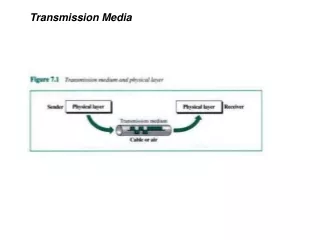
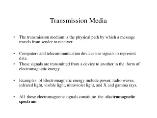
Transmission Media • The transmission medium is the physical path by which a message travels from sender to receiver. • Computers and telecommunication devices use signals to represent data. • These signals are transmitted from a device to another in the form of electromagnetic energy. • Examples of Electromagnetic energy include power, radio waves, infrared light, visible light, ultraviolet light, and X and gamma rays. • All these electromagnetic signals constitute the electromagnetic spectrum
Not all portion of the spectrum are currently usable for telecommunications • Each portion of the spectrum requires a particular transmission medium
Signals of low frequency (like voice signals) are generally transmitted as current over metal cables. It is not possible to transmit visible light over metal cables, for this class of signals is necessary to use a different media, for example fiber-optic cable.
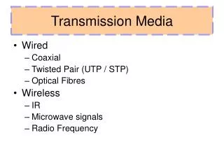
Transmission Media • Guided media, which are those that provide a conduit from one device to another. • Examples: twisted-pair, coaxial cable, optical fiber. • Unguided media (or wireless communication) transport electromagnetic waves without using a physical conductor. Instead, signals are broadcast through air (or, in a few cases, water), and thus are available to anyone who has a device capable of receiving them.
Guided Media There are three categories of guided media: • Twisted-pair cable • Coaxial cable • Fiber-optic cable
Twisted-pair cable • Twisted pair consists of two conductors (normally copper), each with its own plastic insulation, twisted together. • Twisted-pair cable comes in two forms: unshielded and shielded • The twisting helps to reduce the interference (noise) and crosstalk.
Unshielded Twisted-pair (UTP) cable • Any medium can transmit only a fixed range of frequencies! • UTP cable is the most common type of telecommunication medium in use today. • The range is suitable for transmitting both data and video. • Advantages of UTP are its cost and ease of use. UTP is cheap, flexible, and easy to install.
The Electronic Industries Association (EIA) has developed standards to grade UTP. • Category 1. The basic twisted-pair cabling used in telephone systems. This level of quality is fine for voice but inadequate for data transmission. • Category 2. This category is suitable for voice and data transmission of up to 2Mbps. • Category 3.This category is suitable for data transmission of up to 10 Mbps. It is now the standard cable for most telephone systems. • Category 4. This category is suitable for data transmission of up to 20 Mbps. • Category 5. This category is suitable for data transmission of up to 100 Mbps.
UTP connectors The most common UTP connector is RJ45 (RJ stands for Registered Jack).
Shielded Twisted (STP) Cable • STP cable has a metal foil or braided-mesh covering that enhances each pair of insulated conductors. • The metal casing prevents the penetration of electromagnetic noise. • Materials and manufacturing requirements make STP more expensive than UTP but less susceptible to noise.
Applications • Twisted-pair cables are used in telephones lines to provide voice and data channels. • The DSL lines that are used by the telephone companies to provide high data rate connections also use the high-bandwidth capability of unshielded twisted-pair cables. • Local area networks, such as 10Base-T and 100Base-T, also used UTP cables.
Coaxial Cable (or coax) • Coaxial cable carries signals of higher frequency ranges than twisted-pair cable. • Coaxial Cable standards: RG-8, RG-9, RG-11 are used in thick Ethernet RG-58 Used in thin Ethernet RG-59 Used for TV
BNC connectors • To connect coaxial cable to devices, it is necessary to use • coaxial connectors. The most common type of connector is the Bayone-Neill-Concelman, or BNC, connectors. There are three • types: the BNC connector, the BNC T connector, the BNC terminator. • Applications include cable TV networks, and some traditional Ethernet LANs like 10Base-2, or 10-Base5.
Optical Fiber • Metal cables transmit signals in the form of electric current. • Optical fiber is made of glass or plastic and transmits signals in the form of light. • Light, a form of electromagnetic energy, travels at 300,000 Kilometers/second ( 186,000 miles/second), in a vacuum. • The speed of the light depends on the density of the medium through which it is traveling ( the higher density, the slower the speed).
The Nature of the Light • Light travels in a straight line as long as it is moving through a single uniform substance. • If a ray of light traveling through one substance suddenly enters another (less or more dense) substance, its speed changes abruptly, causing the ray to change direction. This change is called refraction.
Critical angle • If the angle of incidence increases, so does the angle of refraction. • The critical angle is defined to be an angle of incidence for which the angle of refraction is 90 degrees.
Reflection • When the angle of incidence becomes greater than the critical angle, a new phenomenon occurs called reflection. • Light no longer passes into the less dense medium at all. http://www.phy.ntnu.edu.tw/ntnujava/viewtopic.php?t=32
Optical fibers use reflection to guide light through a channel. • A glass or core is surrounded by a cladding of less dense glass or plastic. The difference in density of the two materials must be such that a beam of light moving through the core is reflected off the cladding instead of being into it. • Information is encoded onto a beam of light as a series of on-off flashes that represent 1 and 0 bits.
Types of Optical Fiber • There are two basic types of fiber: multimode fiber and single-mode fiber. • Multimode fiber is best designed for short transmission distances, and is suited for use in LAN systems and video surveillance. • Single-mode fiber is best designed for longer transmission distances, making it suitable for long-distance telephony and multichannel television broadcast systems.
Propagation Modes (Types of Optical Fiber ) • Current technology supports two modes for propagating light along optical channels, each requiring fiber with different physical characteristics: Multimode and Single Mode. • Multimode, in turn, can be implemented in two forms: step-index or graded index.
Multimode: In this case multiple beams from a light source move through the core in different paths. • In multimode step-index fiber, the density of the core remains constant from the center to the edges. A beam of light moves through this constant density in a straight line until it reaches the interface of the core and cladding. At the interface there is an abrupt change to a lower density that alters the angle of the beam’s motion. • In a multimode graded-index fiber the density is highest at the center of the core and decreases gradually to its lowest at the edge.
Single mode uses step-index fiber and a highly focused source of light that limits beams to a small range of angles, all close to the horizontal. • Fiber Sizes Optical fibers are defined by the ratio of the diameter of their core to the diameter of their cladding, both expressed in microns (micrometers)
Light sources for optical fibers • The purpose of fiber-optic cable is to contain and direct a beam of light from source to target. • The sending device must be equipped with a light source and the receiving device with photosensitive cell (called a photodiode) capable of translating the received light into an electrical signal. • The light source can be either a light-emitting diode (LED) or an injection laser diode.
Fiber-optic cable connectors The subscriber channel (SC) connector is used in cable TV. It uses a push/pull locking system. The straight-tip (ST) connector is used for connecting cable to networking devices. MT-RJ is a new connector with the same size as RJ45.
Advantages of Optical Fiber • The major advantages offered by fiber-optic cable over twisted-pair and coaxial cable are noise resistance, less signal attenuation, and higher bandwidth. • Noise Resistance: Because fiber-optic transmission uses light rather than electricity, noise is not a factor. External light, the only possible interference, is blocked from the channel by the outer jacket.
Advantages of Optical Fiber • Less signal attenuation Fiber-optic transmission distance is significantly greater than that of other guided media. A signal can run for miles without requiring regeneration. • Higher bandwidth Currently, data rates and bandwidth utilization over fiber-optic cable are limited not by the medium but by the signal generation and reception technology available.
Disadvantages of Optical Fiber • The main disadvantages of fiber optics are cost, installation/maintenance, and fragility. • Cost. Fiber-optic cable is expensive. Also, a laser light source can cost thousands of dollars, compared to hundreds of dollars for electrical signal generators. • Installation/maintenance • Fragility. Glass fiber is more easily broken than wire, making it less useful for applications where hardware portability is required.
Unguided Media • Unguided media, or wireless communication, transport electromagnetic waves without using a physical conductor. Instead the signals are broadcast though air or water, and thus are available to anyone who has a device capable of receiving them. • The section of the electromagnetic spectrum defined as radio communication is divided into eight ranges, called bands, each regulated by government authorities.
Propagation of Radio Waves • Radio technology considers the earth as surrounded by two layers of atmosphere: the troposphere and the ionosphere. • The troposphere is the portion of the atmosphere extending outward approximately 30 miles from the earth's surface. • The troposphere contains what we generally think of as air. Clouds, wind, temperature variations, and weather in general occur in the troposphere. • The ionosphere is the layer of the atmosphere above the troposphere but below space.
Ground propagation. In ground propagation, radio waves travel through the lowest portion of the atmosphere, hugging the earth. These low-frequency signals emanate in all directions from the transmitting antenna and follow the curvature of the planet. The distance depends on the power in the signal. • In Sky propagation, higher-frequency radio waves radiate upward into the ionosphere where they are reflected back to earth. This type of transmission allows for greater distances with lower power output. • In Line-of-Sight Propagation, very high frequency signals are transmitted in straight lines directly from antenna to antenna.
Propagation of Specific Signals • VLF Very Low Frequency waves are propagated as surface waves, usually through the air but some times through seawater. VLF waves do not suffer much attenuation in transmission but are susceptible to the high levels of atmospheric noise ( heat and electricity) active at low altitudes. • VLF waves are use mostly for long-range radio navigation and for submarine communication.
LF low frequency waves are also propagated as surface waves. LF waves are used for long-range radio navigation and for radio beacons or navigational locators. • MF Middle frequency signals are propagated in the troposphere. Uses for MF transmissions include AM radio, maritime radio, and emergency frequencies.
HF high frequency signals use ionospheric propagation. These frequencies move into the ionosphere, where they are reflected back to earth. Uses for HF signals include amateur radio, citizen’s band (CB) radio, military communication, long-distance aircraft and ship communication, telephone, telegraph, and fax.
VHF Most very high frequency waves use line-of-sight propagation. Uses for VHF include VHF television, FM radio, and aircraft navigational aid. • UHF Ultrahigh frequency waves always use line-of-sight propagation. Uses for UHF includes UHF television, mobile telephone, cellular radio, and microwave links.
SHF Superhigh frequency waves are transmitted using mostly line-of-sight and some space propagation. Uses for SHF include terrestrial and satellite microwave and radar communication. • EHF Extremely high frequency waves use space propagation. Uses for EHF are predominantly scientific and include radar, satellite and experimental communications.