Download
1 / 23
230 likes | 402 Vues
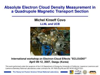
Absolute Electron Cloud Density Measurement in a Quadrupole Magnetic Transport Section. Michel Kireeff Covo LLNL and UCB. International workshop on Electron-Cloud Effects "ECLOUD07" April 09-12, 2007, Daegu (Korea).

E N D
Absolute Electron Cloud Density Measurement in a Quadrupole Magnetic Transport Section Michel Kireeff Covo LLNL and UCB International workshop on Electron-Cloud Effects "ECLOUD07" April 09-12, 2007, Daegu (Korea) This work performed under the auspices of the U.S Department of Energy by University of California, Lawrence Livermore and Lawrence Berkeley National Laboratories under contracts No. W-7405-Eng-48 and DE-AC02-05CH11231.
HIFS e-cloud effort HIFS-VNL Consultants Experiment Michel Kireeff Covo Art Molvik Peter Seidl Frank Bieniosek Joshua Coleman Christian Leister Prabir Roy Simulation Jean-Luc Vay Alex Friedman Ron Cohen Dave Grote Steve Lund Bill Sharp Miguel Furman, Christine Celata (LBNL-Center for Beam Physics) Irv Haber (U. Maryland) R. Davidson, L. Grisham, I. Kaganovich, H. Qin, A. Sefkow, E. Startsev, et al (PPPL) Peter Stoltz, Seth Veizer (Tech-X Corp.) John Verboncoeur (UC-Berkeley)
Outline • E-cloud issues and tools • Retarding Field Analyzer • Electron mode • Ion mode • E-cloud density measurement • Conclusions
Heavy Ion Inertial Fusion or “HIF” goal is to develop an accelerator that can deliver beams to ignite an inertial fusion target ~1km 4.0GeV; 94.A/beam; 0.2ms 1.6MeV; 0.63A/beam; 30ms 4.0GeV; 1.9kA/beam; 10ns DT Target Requirements: 3 - 7 MJ x ~ 10 ns ~ 500 Terawatts Ion range: 0.02 - 0.2 g/cm2 1- 10 GeV Ion charge: 7 MJ/few GeV few mCoul For A ~ 200 ~ 10 16 ions ~ 100 beams 1-4 kA / beam Near term goal: Warm dense matter physics (WDM)
e- e- e- i+ halo e- e- e- Sources of electron and gas clouds e- g • i+ = ion • e-= electron • g = gas • = photon = instability i+ Positive Ion Beam g e- Pipe • Ionization of • background gas • desorbed gas Primary: Secondary: • ion induced emission from • expelled ions hitting vacuum wall • beam halo scraping • photo-emission from synchrotron radiation (HEP) • secondary emission from electron-wall collisions
HCX beam features Fill Factor = 60% Characteristics: • Do not have synchrotron radiation and electron multipacting, but • Have large beam interaction with background gas and walls Faraday Cup Current 1 MeV K+ 180 mA 5 µS 0.1 Hz Electron Clouds are an issue
The High Current Experiment (HCX) is a small, flexible heavy-ion accelerator (at LBNL) Q1 Q2 Q3 Q4 (B) (C) (A) Gas/Electron Experiments MATCHING SECTION ELECTROSTATIC QUADRUPOLES INJECTOR 2 m long MAGNETIC QUADRUPOLES 1 MeV, 0.18 A, 6x10¹² K+/pulse, t ≈ 5 s, 2 kV beam potential 2 m Clearing electrodes remove electrons Retarding Field Analyser (RFA) Suppressor K+ e- End plate Quadrupole magnets Q1 - Q4 for beam transport
Outline • E-cloud issues and tools • Retarding Field Analyzer • Electron mode • Ion mode • E-cloud density measurement • Conclusions
Outline • E-cloud issues and tools • Retarding Field Analyzer • Electron mode • Ion mode • E-cloud density measurement • Conclusions
Ion-induced electron energy distribution is Maxwellian • Method 1: Gas electron source diagnostic • The grid surrounding the target was used to filter ion-induced electron energy from K+ ion impact on the stainless steel target Te= 29.9 eV • Method 2: RFA diagnostic • The retarding grid of a RFA was used to measure the energy distribution of electrons produced and/or expelled at the end of the beam Te= 27.7 eV • Method 3: Clearing Electrode diagnostic • An external C-shaped clearing electrode positively biased was used to suppress electrons from entering a RFA, working as an energy filter Te= 27.77 eV
Outline • E-cloud issues and tools • Retarding Field Analyzer • Electron mode • Ion mode • E-cloud density measurement • Conclusions
RFA measures energy distribution of expelled ions* • Potential of beam edge is ~1000 V, and beam axis is ~ 2100 V Current (A) Charge (pC) Charge (pC) Retarding grid bias (V) Time (s) * M. Kireeff Covo et al., accepted for publication in Nucl. Instrum. Methods Phys. Res. A .
RFA measures total cross sections (ionization + charge exchange) Total Cross Section (m2) Potential (V) Time (us) Time (us) Summary of Total Cross Sections (m2) Ionization Energy (eV)
Outline • E-cloud issues and tools • Retarding Field Analyzer • Electron mode • Ion mode • E-cloud density measurement • Conclusions
Illustrative “beam potential versus time” raw data Ion energy does not surmount the retarding grid bias
/RFA Pb= initial beam potential Pe= Pb– depressed beam potential Neutralization = Pe *1.64 + initial neutralization Pb A first time-dependent measurement of absolute electron cloud density* (I) Retarding field analyzer (RFA) measures beam potential on axis *M. Kireeff Covo et al., Phys. Rev. Lett. 97, 054801 (2006).
/RFA Ie λe = Vd λe Neutralization = λb where: Ie – electron current Vd – electron drift velocity λe – electron line charge density λb – beam line charge density A first time-dependent measurement of absolute electron cloud density* (II) Clearing electrode measures electron current *M. Kireeff Covo et al., Phys. Rev. Lett. 97, 054801 (2006).
/RFA A first time-dependent measurement of absolute electron cloud density* (III) Comparison of the Beam Neutralization inferred from RFA and clearing electrodes *M. Kireeff Covo et al., Phys. Rev. Lett. 97, 054801 (2006).
Outline • E-cloud issues and tools • Retarding Field Analyzer • Electron mode • Ion mode • E-cloud density measurement • Conclusions
Conclusions • • The RFA demonstrated to be a versatile tool that allowed to: • Measure ion and electron energy distribution; • Determine beam-background gas interaction cross section; • Benchmark simulation tools, enabling to model experiments with high fidelity; and • Obtain first absolute measurement of electron cloud density in a magnetic transport section.