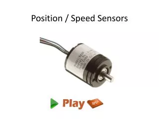
Position Sensors
630 likes | 1.91k Vues
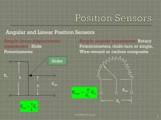
E out. E s. Position Sensors. Angular and Linear Position Sensors. Simple linear displacement transducers : Slide Potentiometer. Simple angular transducers: Rotary Potentiometers, multi-turn or single, Wire-wound or carbon composite. Slider. E s. L. E out. x.

Position Sensors
E N D
Presentation Transcript
Eout Es Position Sensors Angular and Linear Position Sensors Simple linear displacement transducers: Slide Potentiometer Simple angular transducers: Rotary Potentiometers, multi-turn or single, Wire-wound or carbon composite Slider Es L Eout x et438b-5a.pptx
Potentiometer Resolution Wire-wound potentiometers do not have infinite resolution due to wire diameter Resistance varies with position Cross section Number of turns per unit length determines resolution of the potentiometer Resolution (%) = 100/N Where N = number of turns in the pot. et438b-5a.pptx
Potentiometer Loading Error Rp = total potentiometer R aRp = fraction of potentiometer R from wiper to ground Solve using voltage division Es Req Rp + aRp E0 RL Loading error LE defined as = aEs -Eout - RL is load on potentiometer. Must include in calculation Percent Loading Error et438b-5a.pptx
Potentiometer Loading Example Problem Statement A linear wire-wound potentiometer has a total resistance of 50,000 ohms The voltage output of the potentiometer will be converted to a digital value by a 12 bit ADC. Determine minimum number of turns required so that the resolution of the potentiometer does not exceed the quantization error of the ADC. What percent loading error can be expected if the input resistance of the ADC is 100 kW and the range of measurement is from 20% to 80% of the potentiometer value? et438b-5a.pptx
Example Solution Find the resolution of the 12-bit ADC then convert it to a percentage. Assume 1 volt range et438b-5a.pptx
Example Solution (cont.) Loading error depends on position of potentiometer et438b-5a.pptx
Linear Variable Differential Transformers (LVDTs) Note: dots indicates instantaneously positive voltages in transformers Secondary Primary Vp must be AC typical frequency 50k - 15 kHz Vs1 Ls1 Vp Lp Core Motion causes Vs1 and Vs2 to change Vs2 Ls2 Lp and Ls1 coupled Vs1 Increasing Lp and Ls2 coupled Vs2 Increasing Movable Core et438b-5a.pptx
LVDT Output Output V Coils connected so voltages subtract V out + 0 0.06 + - 0.06 Core Position - + core position V out - opposite phase core coupling Lp and Ls2 core coupling Lp and Ls1 core neutral et438b-5a.pptx
Rotory Position TransducerSynchro Systems Three parts to system 1.) Control Transmitter 2.) Control Transformer 3.) Control Differential Vout Control transmitter Control transformer ac source + time Vout - Sinusoidal output with maximum value from this position et438b-5a.pptx
Synchro Systems Control transmitter Control transformer ac source ac - + Vout Output voltage is zero when rotors in this position et438b-5a.pptx
Synchro Systems ac source Control transmitter Control transformer - ac Vout + Output voltage 180 degrees out of phase from initial position et438b-5a.pptx
Synchro Systems Output voltage magnitude is a function of the angular displacement between the control transmitter and the control transformer WhereEm= the maximum amplitude of excitation q= the angular position difference between the transmitter and the transformer rotor w= frequency of excitation voltage et438b-5a.pptx
Synchro Systems Control differential transformer can be added to add constant phase shift. Sending and receiving devices will have a constant angular difference given by the value of qd. System can be used to maintain a constant position difference between two shafts. It can also be used to keep two shafts synchronized. et438b-5a.pptx
Synchro Example A syncho system operates at a frequency of 400 Hz. The maximum amplitude of the transformer rotor voltage is 22.5 V. Determine the ac error signal produced by each of the following pairs of angular displacements a.) q= 90°qd=0° b.) q= 60°qd=0 c.) q= 135°qd=-15° d.) q= 100°qd=-45° At 400 Hz a.) b.) et438b-5a.pptx
Synchro Example (Cont.) et438b-5a.pptx
Velocity Measurements Angular and Linear Velocity Angular Velocity Measurement Methods - dc tachometer - ac tachometer - optical tachometer DC tachometer Dc generator using permanent magnets for field flux N S Field Poles Magnetic Field Brushes and Commutators et438b-5a.pptx
Velocity Measurements Dc Tachometer Tachometer produces a dc voltage that is proportional to angular velocity Proportionality constant = emf constant KE (V/rpm) KE depends on the construction of tachometer Where E = tachometer output (V) KE= emf constant s = angular velocity (rpm) w= angular velocity (rad/s) R = average radius (m) B = flux density (Wb/m2) N = number of conductors L = length of conductor in field (m) emf constant Induced emf et438b-5a.pptx
Velocity Measurements Dc Tachometer Example: A dc tachometer has the following parameters R = 0.03 m N = 220 L = 0.15 m B = 0.2 Wb/m2 Find KE and the output voltage at the following speeds s = 1000, 2500, and 3250 rpm For s = 1000 rpm For s= 2500 rpm And 3250 rpm et438b-5a.pptx
Velocity Measurements Ac Tachometer Ac Tachometers Construction : a 3-phase alternator with a 3-phase rectifier to convert the output to dc. Must have constant field excitation - Permanent magnet field. Non-linear at low speeds due to the forward drop of diodes Limited to lower speed ranges due to this. Range 100-1 Ac Tachometers can also produce a variable frequency output that has a constant voltage. Use frequency-to-voltage conversion to get proportional dc et438b-5a.pptx
Optical Tachometers Digital encoder attached to shaft produces a sequence of pulses. 3 light sensors 3 light sources Encoder tracks Inner – locates home Middle - gives direction info Phase shift between outer and middle tracks Middle leads or lags outer based on direction et438b-5a.pptx
Optical Tachometer Operation Optical Tachometers Pulses counted over time interval. Counter is then reset. The number of pulses counted in interval is proportional to the angular velocity Formulas Where s = shaft speed (rpm) N = number of pulses per shaft revolution C = total count during time period Tc = counter time interval (sec) et438b-5a.pptx
Optical Tachometer Example Incremental encoder produces 2000 pulses/rev. a.) determine count produced by shaft speed of 1200 rpm with a count interval of 5 mS b.) determine the speed measured at a count of 224 for a timer interval of 5 mS a.) Number of counts for 1200 rpm speed b.) Speed for 224 counts et438b-5a.pptx
Acceleration Measurement Definition - acceleration is rate of change of velocity Sensing Methods Newton’s Law f = Ma Where: f = force acting on body M = mass of body a = acceleration Can measure acceleration by measuring force required to accelerate known mass. For angular acceleration, differentiate the velocity signal from velocity sensors et438b-5a.pptx
Acceleration Measurement Sensing Methods For angular acceleration, differentiate the velocity signal from velocity sensors For sampled data systems, derivative is given by difference of readings Where at = acceleration at time t vt-1 = velocity sample at t-1 vt = velocity sample at t Ts = sampling time et438b-5a.pptx
Accelerometers General Structure Springs K/2 Mass Accelerometer attached to device under test and experiences same acceleration as measured object. Motion of mass damped by viscous fluid around mass M Theory of operation same for Integrated devices. K/2 Applications Gaming Automotive Appliance control Disk Drive protection Bearing Condition Monitoring Springs Displacement Sensor (LVDT) et438b-5a.pptx
Accelerometers Accelerometer forms a second order mechanical system. Accelerometer in action For small deflections, spring force offsets force due to acceleration so.... Kx= Ma Which gives x = (M/K)a so acceleration is proportional to displacement Displacement caused by acceleration f = Ma Direction of acceleration et438b-5a.pptx
Accuracy of Acceleration Measurements Acceleration is dynamic measurement, interested in a(t), acceleration as function of time. Consider second order response Wherefo = resonant frequency of accelerometer (Hz) z = damping ratio K = spring constant (N/m) M = mass (Kg) b = damping constant (N-s/m) fa = max. frequency of a(t) et438b-5a.pptx
Accuracy of Acceleration Measurements Accuracy of response related to resonant frequency of device Must have sufficient range to measure changes if fa << fo then measurements will be accurate if fa >>fothen the mass does not have time to react incorrect measurement fa = fo then displacement is greatly exaggerated incorrect measurement Make fo at least 2.5 times greater than fa max for < 0.5% error et438b-5a.pptx
Accelerometer Example The accelerometer shown below has the following specifications: M = 0.0156 kg K = 260 N/m b = 2.4 N-s/m xmax= +- 0.3 cm K/2 b Find the following a.) maximum acceleration that can be measured b.) resonant frequency c.) damping ratio d.) maximum frequency that can be used with 0.5% error or less M K/2 et438b-5a.pptx
Accelerometer Example M = 0.0156 kg K = 260 N/m b = 2.4 N-s/m xmax= +- 0.3 cm K/2 a.) b M b.) K/2 c.) d.) Maximum frequency of a(t) with 0.5% error is….. et438b-5a.pptx