CSE 381 – Advanced Game Programming 3D Mathematics
580 likes | 1.16k Vues
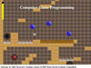
CSE 381 – Advanced Game Programming 3D Mathematics. Pong by Atari, released to public 1975. So what math do games use?. All types geometry & trig for building & moving things linear algebra for rendering things calculus for performing collision detection and lots, lots more:

CSE 381 – Advanced Game Programming 3D Mathematics
E N D
Presentation Transcript
CSE 381 – Advanced Game Programming3D Mathematics Pong by Atari, released to public 1975
So what math do games use? • All types • geometry & trig for building & moving things • linear algebra for rendering things • calculus for performing collision detection • and lots, lots more: • Numerical methods • Quaternions • Curves • Surfaces • NURBS • Etc.
What math should we cover? • Today: • Vector Math • Matrix Math • Another time: • Plane equations and frustum culling • Quaternions
What unit of measurement should we use? • Most games use: • meters • precision down to millimeters • maximum range to 100 kilometers • Get on the same page: • programmers • artists • level designers
3D Coordinate Systems • Use: • x, y, z to locate items (like vertices) • floating point values http://img139.imageshack.us/i/viewportgy6.gif/#q=3d%20coordinate%20system%20maya
Right Handed vs. Left Handed • Vertices arranged counter-clockwise +y +y +x +x +z +z • Vertices arranged clockwise
Coordinate System Conversions • Problem: • art program built models using right-handed system • game engine uses left-handed system • Solution • Reverse the order of vertices on each triangle • Multiply each Z-coordinate by -1
It all starts with vectors • What’s a vector? • a direction • What are vectors used for? • everything • graphics & physics calculations • Things we must learn: • Unit vectors • Vector normalization • Vector mathematics (3, 4, 0)
What’s a Unit Vector? • Any vector that has a length of 1.0 • may be created by vector normalization • Think of it as a direction with a standard magnitude • it’s useful for many computations • Ex: inputs to cross & dot products • How might we normalize a vector? • divide the vector by its length
Vector Normalization Example • V = (3, 4, 0) • LengthV = square_root(32 + 42 + 02) = square_root(25) = 5 • Unit VectorV = (3/5, 4/5, 0/5) = (.6, .8, 0)
And now for some Vector Math • Vector Arithmetic • addition & Subtraction • for combining vectors • Dot Product • for calculating angles • Cross Product • for calculating direction (another vector)
Vector Arithmetic • Adding or subtracting each component of 2 vectors • Useful for: • combining velocities in physics calculations • collision detection algorithms V1 + V2 = {(V1x + V2x), (V1y + V2y), (V1z+ V2z)} V1 - V2 = {(V1x - V2x), (V1y - V2y), (V1z - V2z)}
Dot Product • Projects one vector onto the other and calculates the length of that vector • Useful for: • determining whether an angle is acute, obtuse, or right • Is a surface facing toward the camera or not? V1 ∙ V2 = (V1x * V2x) + (V1y * V2y) + (V1z * V2z) • arccos of V1 ∙ V2 gives you the angle
Dot Product Results to Note V1 ∙ V1 = 1 V1 ∙ V2 = 0 if: V1 is orthogonal to V2, meaning V1 & V2 form a right angle to each other and they are the same length V1 ∙ V2 = -1 if: V1 and V2 are the same length and are pointing away from each other
Dot Product Visualization V1 V1 V2 V2 V1 ∙ V2 = -1 V1 ∙ V2 > 0 V1 V1 V2 V2 V1 ∙ V2 = 0 V1 ∙ V2 < 0 V1 ∙ V2 == V2 ∙ V1
Dot Product Back Face Culling • Camera has look-at vector (V1) • unit vector • All surfaces have a normal vector (V2) • orthogonal to plane of polygon • If V1 ∙ V2 < 0, the polygon is facing the camera • And so should be drawn
Cross Product • Produces a vector orthogonal to the plane formed by two input vectors • Useful for: • Calculating normal vector of a polygon V1 X V2 = { (V1.y * V2.z) – (V2.y * V1.z), (V1.z * V2.x) – (V2.z * V1.x), (V1.x * V2.y) – (V2.x * V1.y) }
Cross Product Visualization V3 V1 V1 V2 V1 X V2 = V3 V2 V2 X V1 = V3 V1 V3 V2 V1 X V2 = NULL V1 X V2 ≠ V2 X V1
The Need for Matrix Mathematics • We store model vertices & normals with their original modeled values • We filter them through transformation matrices • moves it from model to world space • Each model has a transform that factors: • translation • rotation • scaling
Multiple Similar Models • Suppose I want 2 ogres • What will they have in common? • geometry • texturing (perhaps some variations) • Animations • etc. • What will they have that’s unique? • transform matrix • animation state • etc.
Asset Design Pattern • Use 2 classes: • ModelType • stores everything common to all models • vertex buffers, index buffers, texture coordinates, etc. • Model • stores everything common to a single model • position, rotation, etc. • has unique transform matrix built from position, etc. • update matrix each frame
Think of it this way • To render 2 models, each frame: • Update transform matrix for model 1 • Load the transform matrix for model 1 • Render model 1 • Update transform matrix for model 2 • Load the transform matrix for model 2 • Render model 2 Etc.
So what’s a model’s transform matrix? • A 4 X 4 array of floating point numbers • They are really shorthand for representing linear equations • Components we’ll see: • Translation • moves the object to a location in world space • Rotation • rotates the object around an origin
Translation • T.x, T.y, T.z will move the object to that location in world space 1 0 0 0 0 1 0 0 0 0 1 0 T.x T.y T.z 1
Rotations are more complicated • There are 3 kinds of rotation matrices: • one around the x-axis • one around the y-axis • one around the z-axis • The object would be rotated about each axis by some angles: θx, θy, θz • We need to factor all 3 rotations of course
X-axis Rotation Matrix 1 0 0 0 0 cos(θ) –sin(θ) 0 0 sin(θ) cos(θ) 0 0 0 0 1
Y-axis Rotation Matrix cos(θ) 0 sin(θ) 0 0 1 0 0 –sin(θ) 0 cos(θ) 0 0 0 0 1
Z-axis Rotation Matrix cos(θ) -sin(θ) 0 0 sin(θ) cos(θ) 0 0 0 0 1 0 0 0 0 1
Now we need to combine them • Ultimately, for each object, we want only one matrix • encode all operations into it • How do we do this? • matrix multiplication • A 4X4 Matrix X A 4X4 Matrix gives you another 4X 4 Matrix
Note, order of operations matters • Start with identity matrix • Multiply by rotation matrices first • Multiply by translation matrix last
Matrix Multiplication • How about M X N? M11 M12 M13 M14 M21 M22 M23 M24 M31 M32 M33 M34 M41 M42 M43 M44 N11 N12 N13 N14 N21 N22 N23 N24 N31 N32 N33 N34 N41 N42 N43 N44 * P11 P12 P13 P14 P21 P22 P23 P24 P31 P32 P33 P34 P41 P42 P43 P44 =
How does that work? M11 M12 M13 M14 M21 M22 M23 M24 M31 M32 M33 M34 M41 M42 M43 M44 N11 N12 N13 N14 N21 N22 N23 N24 N31 N32 N33 N34 N41 N42 N43 N44 * P11 P12 P13 P14 P21 P22 P23 P24 P31 P32 P33 P34 P41 P42 P43 P44 =
Calculating P P11 = M11*N11 + M12*N21 + M13*N31 + M14*M41 P12 = M11*N12 + M12*N22 + M13*N32 + M14*M42 P13 = M11*N13 + M12*N23 + M13*N33 + M14*M43 P14 = M11*N14 + M12*N24 + M13*N34 + M14*M44 P21 = M21*N11 + M22*N21 + M23*N31 + M24*M41 P22 = M21*N12 + M22*N22 + M23*N32 + M24*M42 P23 = M21*N13 + M22*N23 + M23*N33 + M24*M43 P24 = M21*N14 + M22*N24 + M23*N34 + M24*M44 P31 = M31*N11 + M32*N21 + M33*N31 + M34*M41 P32 = M31*N12 + M32*N22 + M33*N32 + M34*M42 P33 = M31*N13 + M32*N23 + M33*N33 + M34*M43 P34 = M31*N34 + M32*N24 + M33*N34 + M34*M44 P41 = M41*N11 + M42*N21 + M43*N31 + M44*M41 P42 = M41*N12 + M42*N22 + M43*N32 + M44*M42 P43 = M41*N13 + M42*N23 + M43*N33 + M44*M43 P44 = M41*N14 + M42*N24 + M43*N34 + M44*M44
What do we do with our matrix? • Transform Points • put point into 4 X 1 vector • put 1 in 4th cell • multiply transform by point matrix • result is point in world space coordinates • Transform Normal Vectors • put vector into 4X1 vector • put 0 in 4th cell • multiply transform by point matrix • result is vector in world space coordinates
Transforming a Point M11 M12 M13 M14 M21 M22 M23 M24 M31 M32 M33 M34 M41 M42 M43 M44 Px Py Pz 1 * P11 P21 P31 P41 =
So were does this come in? Full Game World Scene Graph Culling Models Near Camera Frustum Culling Models In Frustum Rendering • Transform vertices • Texturing • Etc.
Frustum Culling • Try reading the following: • http://www.lighthouse3d.com/opengl/viewfrustum/index.php?intro • http://www2.ravensoft.com/users/ggribb/plane%20extraction.pdf • http://www.flipcode.com/archives/Frustum_Culling.shtml
So how do we do frustum culling? • One approach: • First, extract frustum planes • calculate 8 frustum points • use cross-products to calculate orthogonal vectors • Second, calculate the orthogonal vector from each plane to the object’s center • this step’s a bit tricky • Third, determine which side the object is on for each plane • dot product
A better approach • First, extract frustum planes • calculate 8 frustum points • use cross-products to calculate orthogonal vectors • Second, calculate the signed distance from the point to the plane • much easier • Third, determine which side the object is on for each plane • examine sign of result from step 2
How do we extract the frustum planes? • What do we know? • camera position • camera look-at-vector • camera up-vector • viewport (front clipping plane) width & height • distances from camera to near & far clipping planes • What do we need to know? • 8 frustum points • front-top-right, front-bottom-right, front-top-left, front-bottom-left • back-top-right, back-bottom-right, back-top-left, back-bottom-left
How can we calculate those points? • Assumptions: • right-handed coordinate system • camera at origin (0,0,0) • camera look-at is (1, 0, 0) • camera up is (0, 1, 0) • Easy, simple arithmetic: • front-top-right = (near, height/2, width/2) • front-bottom-right = (near, -height/2, width/2) • front-top-left = (near, height/2, -width/2) • front-bottom-left = (near, -height/2, -width/2) • back-top-right = (far, height/2, width/2) • back-bottom-right = (far, -height/2, width/2) • back-top-left = (far, height/2, -width/2) • back-bottom-left = (far, -height/2, -width/2) Calculate these values once, at start of game
How do we get the plane normals? • Cross Product • Using what vectors? • those between 3 points on each plane • Note, be careful, remember for cross-product: A X B ≠ B X A
What happens when the camera moves? • We need to update stuff. Like what? • look at vector • up vector • right vector • frustum points (8 corners) • frustum normals • Note: beware floating point error • don’t change the original values • use copies of original each frame • recalculate from same base point each frame
How do we update these values? • Using a transformation matrix • What’s the translation for this matrix? • camera position • What’s are the rotations for this matrix? • camera’s rotation
And plane to point distance? • First we need plane equations • We can define a plane as: Ax + By + Cz + D = 0 • A, B, & C are the plane’s normal vector components • D is the distance from origin • 0 for left/right/top/bottom planes • near for near plane, far for far plane • but this is for a camera at origin
But the frustum moves • Same old wrinkle • Solution: • extract plane information from transformation matrix • See http://www2.ravensoft.com/users/ggribb/plane%20extraction.pdf
What do we do with our plane equations? • Simply plug-in the coordinates of the object’s center into the plane equation • The result is the signed distance from the plane to the point • To get the true distance, then normalize the vector • What we really care about is the sign of the distance
Make your decision • If distance < 0 , then the point p lies in the negative halfspace. • If distance = 0 , then the point p lies in the plane. • If distance > 0 , then the point p lies in the positive halfspace.
Yaw, Pitch, & Roll • An object can be rotated about all 3 axes http://mtp.jpl.nasa.gov/notes/pointing/Aircraft_Attitude2.png
Quaternion • An alternative for representing rotations • Can provide certain advantages over traditional representations: • require less storage space • concatenation of quaternions require fewer arithmetic operations • more easily interpolated for producing smooth animation