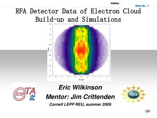
Electron Cloud Simulations for DA F NE
340 likes | 600 Vues
Electron Cloud Simulations for DA F NE. T. Demma INFN-LNF Thanks to K. Ohmi (KEK) Work supported in part by the “Ministero degli Affari Esteri, Direzione Generale per la Promozione e la Cooperazione Culturale”. Plan of talk. Introduction ECLOUD Simulations for the DAFNE wiggler

Electron Cloud Simulations for DA F NE
E N D
Presentation Transcript
Electron Cloud Simulations for DAFNE T. Demma INFN-LNF Thanks to K. Ohmi (KEK) Work supported in part by the “Ministero degli Affari Esteri, Direzione Generale per la Promozione e la Cooperazione Culturale”
Plan of talk • Introduction • ECLOUD Simulations for the DAFNE wiggler • Secondary Emission Yield • bunch patterns • magnetic field models • ECLOUD Simulations for build up in presence of solenoidal field • Preliminary analysis of the instabilities • Conclusions
Electron cloud at DAFNE • e+ current limited to 1.2 A by strong horizontal instability • Large positive tune shift with current in e+ ring, not seen in e- ring • Instability depends on bunch current • Instability strongly increases along the train • Anomalous vacuum pressure rise has been oserved in e+ ring • Instability sensitive to orbit in wiggler and bending magnets • Main change for the 2003 was wiggler field modification
Wiggler vacuum chamber A. Chimenti et Al., Proc. Of PAC 93 Wiggler vacuum chamber cross section Wiggler beam chamber detail • Al alloy 5083-H321 chamber (120 mm x 20 mm ) • 10 mm slots divide the beam channel from the antechambers where absorbers and pumping stations are located • 95% of photon flux is intercepted in the antechambers
Wiggler magnetic field model in ECLOUD simulations M. Preger, DAFNE Tech. Note L-34; C.Vaccarezza, PAC05, p.779 magnetic field (Bx, By, Bz) inside the wiggler as a function of x,y,z coordinates is obtained from a bi-cubic fit of the measured 2-D field-map data By (x,y=0,z); field components Bx and Bz are approximated by consistent with Maxwell’s equations:
peak field ~1.7 T period ~0.65 m x=-6 cm, x= 0 cm, x= +6 cm By[T] z[m] Bz[T] Bx[T] z [m] z[m] Wiggler magnetic field
Input parameters for ECLOUD (DAFNE Wiggler 2003) * As measured on Al sampels with same finishing of the actual vacuum camber N.Mahne et Al. , PAC’05
Bunch patterns Nb=2.1 1010 100 bunches Lsep= 0.8 m 50 bunches Lsep= 1.6 m 33 bunches Lsep= 2.4 m 25 bunches Lsep= 3.2 m
Secondary emission yield maximum (δmax) δmax=1.9 δmax =1.7 δmax =1.5 δmax =1.3 δmax =1.1 100 bunches (Nb= 2.1x10¹⁰ ; Lsep=0.8m; Ngap= 20)
Electron reflectivity at 0 energy δ0 = 100 % Nb=2.1 1010 100 bunches Lsep= 0.8 m 50 bunches Lsep= 1.6 m 33 bunches Lsep= 2.4 m 25 bunches Lsep= 3.2 m
Magnetic field models By[T] z[m] 100 bunches, Lsep= 0.8 m, Nb=2.1 1010 2003 wiggler2002 wiggler 2007 wiggler (proposed)
Solenoids Installation • At the startup after the recent shutdown for the setup of the crab waist collision scheme the instability threshold dropped to 270mA for the positron current (feedback switched off). • Main change was the installation of new interaction regions (20 m straight sections of alluminum SEY>2) • In the attempt to find a remedy solenoids were installed in the field free regions of DAFNE, leading to an increase of the threshold to 400mA (feedback switched off).
Multipacting Suppression Nb=2.1x10¹⁰ Lsep=0.8 m R= 30 mm δmax =2.4 (10f-30e-100f) Bz=0 GBz=10 G Bz=20 G Bz=40 G Photoelecrons are produced only during the passage of the first 10 bunches.
x-y Phase-Space Snapshot Bz=40 G
Effects of Solenoids on Vacuum Pressure Rise (100f,20e) Lsep=0.8 m Bz= 40 G Sol. Off/Sol. On Vacuum pressure read-out vs. total current as recorded in a straight section of the positron ring where a 40 G solenoidal field was turned on (blue dots) and off (red dots).
Typical observations of coupled bunch instability • Growth rates depends on bunch current • Most unstable mode is always a slow frequency mode (-1 mode)
PEI-M Tracking simulationK.Ohmi, PRE55,7550 (1997),K.Ohmi, PAC97, pp1667. Electron cloud e+bunches z y ~m x • Solve both equations of beam and electrons simultaneously, giving the transverse amplitude of each bunch as a function of time. • Fourier transformation of the amplitudes gives a spectrum of the unstable mode, identified by peaks of the betatron sidebands.
Bunch train evolution x [m] bunch 1.2 A in 60 equispaced bunches
60 equispaced bunches Beam current 1.2 A Growth time ~ 100 turn Mode spectrum and growth rate -1 mode (60-5-1=54)
e-cloud density evolution 1 turn 5 turn 10 turn 15 turn 20 turn 25 turn
120 equispaced bunches Beam current 1.2 A Growth time ~ 100 turn Mode spectrum and growth rate -1 mode (120-5-1=154)
Summary • ECLOUD build-up simulations for the DAFNE Wiggler show: • expected dependence of e-cloud build-up on SEY parameters • no dependence of e-cloud build-up on magnetic field model • Solenoids were installed at DAFNE, preliminary observation seems to confirm their effectiveness in reducing e-cloud build-up . • Coupled-bunch instability has been simulated using PEI-M for the DAFNE parameters • Preliminary results are in qualitative agreement with grow-damp measurments • Explore a wider range of beam/chamber parameters and different field regions • Compare the results with other codes (Ecloud, POSINST) • Modify the code to include ellyptical boundaries
Instability growth rates Switching off the horizontal feedback for short periods, transverse grow-damp measurements have been performed to estimate the instability growth rates at different beam currents. Horizontal growth rates recorded in July 2004. (A.Drago et Al. Proceedings of PAC 2005) Nb=1.06 · 1010 (100 bunches) Nb=1.5 · 1010 (50 bunches) Nb=1.9 · 1010 (33 bunches) Nb=3.13 · 1010 (25 bunches) 1/~ 8 ms-1
Bunch patterns (fixed growth rate) 100 bunches Nb=1.06 1010 Lsep= 0.8 m 50 bunches Nb=1.5 1010 Lsep= 1.6 m 33 bunches Nb=1.9 1010 Lsep= 2.4 m 25 bunches Nb=3.13 1010 Lsep= 3.2 m
Cyclotron Resonance Y. Cai et Al., Phys. Rev. ST-AB 7, 024402 (2004) • Resonance condition • Intensity threshold (R=33 mm, δmax =2.4 ) (R=44 mm, δmax =1.9 )
Simulated Intensity Threshold Bz=66 G; Lsep Bz=33 G; 2Lsep R=30mm δmax =2.4 Nb5x1010 for both Lsep and 2Lsep is above the DAFNE operated current.
Linear theory of e-cloud induced multibunch instability[S.S. Win et al., Phys. Rev. ST-AB 8, 094401 (2005)] Under linearity and superposition assumption, the momentum kick experienced by bunch i when bunch j is displached can be written as: Coupled bunch instability is characterized by the dispersion relation: Bunches oscillate with a mode characterized by: The momentum kick can calculated numerically using the PEI-M code.
Instability caused by electrons in the DAFNE arcs • Lsep= 0.8 m • bunch 400 is hor. displaced (x0=5mm) • Electron distribution • Wake force • Growth rate ~ 100 turn
Wake linearity dx=5 mm dx=10 mm Linearity is satisfied up to no more than the 410th bunch
![[f´‚nE˘RIks]](https://cdn0.slideserve.com/636013/f-ne-riks-dt.jpg)

![[f´‚nE˘RIks]](https://cdn0.slideserve.com/1072532/f-ne-riks-dt.jpg)


![[f´‚nE˘RIks]](https://cdn2.slideserve.com/5310017/f-ne-riks-dt.jpg)