Download
1 / 32
320 likes | 407 Vues
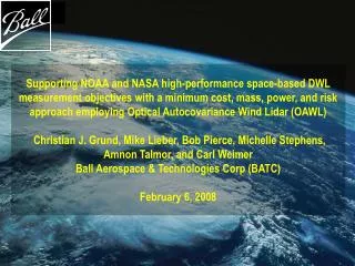
Supporting NOAA and NASA high-performance space-based DWL measurement objectives with Optical Autocovariance Wind Lidar (OAWL) to save cost, mass, power, and complexity while achieving mission goals. Ball Aerospace & Technologies Corp (BATC) is investing in new receiver technology for upcoming NASA missions. References and challenges in developing OAWL technology are discussed.

E N D
Supporting NOAA and NASA high-performance space-based DWL measurement objectives with a minimum cost, mass, power, and risk approach employing Optical Autocovariance Wind Lidar (OAWL) Christian J. Grund, Mike Lieber, Bob Pierce, Michelle Stephens, Amnon Talmor, and Carl WeimerBall Aerospace & Technologies Corp (BATC)February 6, 2008
BATC Objectives and Rationales • OAWL, OA-HSRL • To offer broadened trade space for wind and aerosol profiling technologies addressing NOAA and NASA goals as outlined in the NRC Decadal Survey (3D-winds, ACE, and GACM missions) • OA approach saves mass, cost, volume, complexity, number of lasers, technical risk (e.g. can reuse CALIPSO/MOLA/GLAS telescope design), and mission performance risk (in conjunction with an etalon receiver) • Why is Ball investing in new receiver technology? • We believe this is an enabling approach to achieve a space mission • Target NASA missions start in 2012 (aerosols), but the decisions for the final 3D-wind technology will probably occur in 2010 time frame. Time is now to demonstrate viability of alternatives. • Belief: Cost, weight, power, complexity, and performance issues of current baseline need addressing. • Community vetting and acceptance: OAWL is new, but other technologies have 15-30+ year history. 2006 internal investment • Built proof of concept OAWL system and demonstrated atmospheric wind References: Grund, ” Lidar Wind Profiling from Geostationary Orbit using Imaging Optical Autocovariance Interferometry”, WG on space-based lidar winds 7/2007, Snowmass, CO Grund, et al, “Optical Autocovariance Wind Lidar and Performance from LEO”, 7/2007 Coherent Laser Radar Conference, Snowmass, CO. 2007 internal investment • Designed and modeled an achromatic, field-widened, high-resolution interferometer (1m OPD), suitable for autonomous aircraft operation - successfully completed • Prove OA HSRL with Proof of Concept (POC) hardware, in progress • Built comprehensive space-based OAWL radiometric performance modeling capability 2008internal investment • Fabrication of the robust, multi-wavelength OA receiver design OAWL: Optical Autocovariance Wind Lidar - Doppler wind profiles OA-HSRL: Optical Autocovariance-High Spectral Resolution Lidar - Calibrated Aerosol Profiles
Challenges Coherent Detection Direct Detection Etalons (edge/image) Direct Detection OAWL Transmitter Laser Mode Free of absolute optical frequency lock Single/stable No Single, l-stable No Single/hopping OK Yes Receiver Does not need a stable reference laser Detector elements per profile Single multi-speckle averaging/shot Eliminates orbital velocity correction hardware No 1 No No Yes ~4 / 15 CCD accum. Yes No,Maybe Yes 4 (time independent) Yes Yes Phenomenology Measure Aerosol Measure Molecular Independent of Aer / Mol mixing ratio Full precision 0-20 km profile Yes No Yes No Yes / Yes Yes No Maybe Yes Maybe Yes Yes(integrated with etalons) Multi-mission Compatibilities HSRL (calibrated aerosols/clouds) DIAL (chemical species) Raman (Chemical species, T, P) Photon counting potential (GEO??) No Some No (IR laser) N/A Maybe / Yes Maybe Yes (UV laser) Yes (Difficult ROIC) Yes Yes Yes (UV laser) Yes (Simple ROIC) OAWL Combines/Augments the Best Traits of Both Coherent and Incoherent Lidar Methods Green=positive, Red=negative, yellow=qualified Ball Aerospace & Technologies
2007 Phase 3:Design a Robust , Field-widened, Achromatic Receiver Suitable for Airborne Testing
Proof of Concept (POC) OAWL System Demonstrated 1 m/s Precision in Atmospheric Tests Brassboard system: 3 parallel interferometer architecture: • Demonstrated:~1m/s precision with 0.3 s averaging and 3m range resolution in atmospheric tests at 60 m, agreeing with model predictions • POC Limitations: • Rooftop range safety limited to 100m • Low power COTS laser limits range • 50% light measured by 3 detectors: simple for POC, but not efficient • Hard to calibrate due to specific 0-phase sampling implementation Red: OAWL (L); Anemometer-OA cross correlation (R) White: sonic anemometer (L); anemometer autocorrelation (R) Blue: cross correlation for pure Gaussian noise distributions Ball Aerospace & Technologies patents pending
New OAWL Design Uses Polarization Phase Delays and Multiplexing to Implement 4-Phase-Delay Interferometers with the Same Optical Path • Mach-Zehnder-like interferometer allows 100% light detection on 4 detectors • Cat’s-eyes field-widen and preserve interference parity allowing wide alignment tolerance, practical simple telescope optics (ALADIN needs ~5 mR alignment, • Coherent requires l/4, telescope and <3.8 mRalignment (3dB loss)) • Receiver is achromatic, allowing simultaneous multi-l operations (multi-mission capable: Winds + HSRL(aerosols) + DIAL(chemistry)) • Very forgiving of telescope wavefront distortion saving cost, mass, enabling HOE optics for high resolution aerosol measurement • 2 inputs allowing easy calibration Ball Aerospace & Technologies patents pending
Solid Model of Receiver (detector module covers removed) - All aluminum construction minimizes DT, cost - Athermal interferometer design - Factory-set operational alignment for autonomous aircraft operation - ≈100% opt. eff. to detector - multi-l winds, plus HSRL and depolarization for aerosol characterization and ice/water cloud discrimination CDR complete Dec. ‘07 Detectors: 1 532nm depolarization 1 355nm depolarization 4 532nm winds/HSRL 4 355nm winds/HSRL 10 Total Ball Aerospace & Technologies
NASTRAN FEA Evaluation Suggests Interferometer is Robust to WB-57 Vibe Environment
Fringes & phase noise EOSyM Representation of the OA Receiver System • Coupled disturbance/ structure/ optics model built up inside EOSyM (End-to-end Optical System Model) environment. • Time simulation and frequency domain cross-checking for vibration results. • Seismic mass input of disturbances in 3 directions. • Structure outputs 6 optics displacements in 6 DOF to optical model. • Optical model ray trace and sensitivity matrices. Ball Aerospace & Technologies
Code V SolidWorks 6 NASTRAN Aircraft PSD Integrated Model Process Developed at BATC • Goals: • <6 nm (0.11 rad phase error) vibration induced noise), 12 nm accep. • <5% visibility reduction due to thermoelastic distortions. • Main system modeling outputs • Fringe visibility • Phase noise References: M. Lieber, C. Weimer, M. Stephens, R. Demara, “Development of a validated end-to-end model for space-based lidar systems”, in SPIE vol 6681, U.N.Singh, Lidar Remote Sensing for Environmental Monitoring VIII, Aug 2007. M. Lieber, C. Randall, L. Ayari, N. Schneider, T. Holden, S. Osterman, L. Arboneaux, "System verification of the JMEX mission residual motion requirements with integrated modeling", SPIE 5899, Aug 2005. M. Lieber, C. Noecker, S. Kilston, “Integrated system modeling for evaluating the coronagraph approach to planet detection”, SPIE V4860, Aug 2002 Ball Aerospace & Technologies
Example Effect of Vibration and Thermoelastic Structural Distortion • Single pixel detection measures sum of the pupil field intensity (proportional to visibility). Full transmission, in phase Zero transmission, out of phase Piston due to Doppler signal and vibration SE=1 Visibility constant, but phase varies SE=0 Tilts due to Thermoelastic distortion and misalignment + SE=0.28 SE=0.72 Visibility degraded (integral over pupil) Ball Aerospace & Technologies
Pre-flight calibration goal Imax (envelope) = Visibility = Contrast Change of phase error due to structural vibration during time-of-flight dj Short period Flight operating point (slowly drifting) Change due to thermoelastic distortion Long period Visibility and Phase Noise • Visibility loss means decrease in aerosol velocity measurement optical efficiency, and HSRL aerosol/molecular signal separation. • Phase noise emulates wind-induced phase shift of return signal; unimportant to HSRL Ball Aerospace & Technologies
Integrated Model – Design Iteration:Vibration-Induced Phase Noise Convergence on Specification 3.5 1900 nm, initial hard mount 3 40/ 20 nm, 20 Hz isolators added, WC/ nom 8.5/ 6 nm, redesigned structure, WC/ nom 2.5 2 Log OPD (nm) 1.5 Requirement: <1m/s/shot/100 ms Random dynamic error with WB-57 excitation 1 Final design Prediction Feb. 2008 : 6nm RMS jitter, exceeding spec and meeting goal, suggests performance dominated by SNR not environment 0.5 0 1 2 3 4 5 WC = Worst case Thermal results: model verifies design is athermal wrt average temperature Ball Aerospace & Technologies
In Progress and Proposed Efforts to Raise TRL to 5,6 2008 Internally Funded Objective: Fabricate OA Receiver Suitable for aircraft flight testing In-Progress Status: • Optical design PDR - complete Sep. 2007 • Receiver CDR - complete Dec. 2007 • Receiver design /performance modeled - complete Jan. 2008 • Major components to fabrication – in progress Feb. 2008 • System Assembled/ preliminary testing - planned Aug. 2008 Proposals submitted: • NASA ROSES Instrument Incubator Program: • PI Grund (Ball), OA winds. Raise TRL for winds from WB-57, complete OA as a system, flight plan to pass over many wind profiler network sites, potential ground lidar near Boulder, land and ocean • PI Hostetler (NASA LaRC), OA HSRL. Alternative interferometer approach for multi-wavelength HSRL, data collected could be processed for winds, no special corroborative winds in current plan LOOKING FOR OTHER INTERESTS and POSSIBILITIES Ball Aerospace & Technologies
FUTURE CRAD-Proposed Implementation for WB-57 Pallet Cover 6’ Pallet (WB-57 form factor) Custom Pallet-Mounting Frame Telescope IRAD-Built Receiver Laser Source Custom Window Ball Aerospace & Technologies
Comprehensive LEO Performance Model Implemented for Realistic Components LEO Model Parameters: Wavelength 355 nm Pulse Energy 550 mJ Pulse rate 50 Hz Receiver diameter 1m (single beam) LOS angle with vertical 450 Vector crossing angle 900 Horizontal resolution* 70 km (500 shots) System transmission 0.35 Alignment error 5 mR average (NOTE: ~50 mR allowed) Background bandwidth 35 pm Orbit altitude 400 km Vertical resolution 0-2 km, 250m 2-12 km, 500m 12-20 km, 1 km Phenomenology CALIPSO model Validated CALIPSO Backscatter model used. Model calculations validated against short range POC measurements. Ball Aerospace & Technologies
Cloud free LOS “Thres/Demo” Margin “Objective” Margin OAWL Daytime Space-based Performance OPD 1m, optimized for aerosolsWaveform signal processing and 4-channel architecture implemented Ball Aerospace & Technologies
Evaluating Cloud Impacts on OA Wind Accuracy: 1st Cut • No biases due to aerosol to molecular backscatter mixing ratioclouds induce no velocity biases • Sliding range gate feasible independence from range-backscatter weighting errors • Every shot 0-referenced no dependence on changes in laser spectrum over shot averaging time • Gradual degradation as signals decrease due to opaque cloud fraction or translucent cloud OD: If ODmargin = ODcloud that degrades velocity precision to the available margin then, for OAWL: • ODmargin for“objective” performance is ~0.46 • ODmargin for “demo/target” performance is ~0.81 Conclusions: for the OA model assumptions, if the LOS cloud attenuation over profile integration time averages to: • OD<0.46, then objective requirements are still met 100% in the PBL • OD<0.81, thendemo/thresholdrequirements are still met 100% in the PBL • For OD>0.81, performance degrades slowly with effective cloud OD as per above equation Running an OSSE would be a good next step to include global statistics. Where N is the number of shots in the profile average, ODcloud is the optical depth of the cloud in each shot above the altitude of interest, and Ve is the cloud free velocity error. (might apply to all direct detection lidars if SNR behaves) Ball Aerospace & Technologies
Integrated Direct Detection (IDD) Lidarfor Aerosol and Molecular Backscatter Winds
A Single-laser All Direct Detection Solution: Couple OAWL and Etalon receivers Integrated Direct Detection (IDD) wind lidar approach: • OAWL uses most of the aerosol component, rejects molecular. • OAWL HSRL retrieval determines residual aerosol/molecular mixing ratio • Etalon backend processes molecular backscatter winds, corrected by HSRL • Result: • single-laser transmitter, single wavelength system • single simple, low power and mass signal processor • full atmospheric profile using aerosol and molecular backscatter signals Ball Aerospace patents pending Molecular WindsUpper atmosphere profile Etalon Molecular Receiver OAWL Aerosol Receiver Combined Signal Processing Telescope 1011101100 Full Atmospheric Profile Data Aerosol Winds Lower atmosphere profile UV Laser HSRL Aer/mol mixing ratio Ball Aerospace & Technologies
IDD Receiver vs. ALADIN ALADIN Approach: 355nm Laser CCD Accumulation Profiling Detectors Common Rec/Trans Telescope Fizeau Fringe-Imaging Aerosol Receiver Shutter QE advantage but signal accumulation precludes per-shot corrections; frequency stability of laser must extend over shot accumulation time. Double-Edge Etalon Molecular Receiver Very small FOV and high receiver / transmitter alignment tolerance are driven by Fizeau resolution and background light accumulation in detectors. High wavefront quality needed to support small FOV. Precludes HOE scanner/telescope. Proposed OAWL/Etalon IDD Approach: • Shot-resolved detectors support: • Simplified laser • minimized background light • photon-counting, sliding range gate • software-only LOS velocity correction • detector system redundancy 355nm Laser Double-Edge Etalon Molecular Receiver Receiver Telescope Per-shot profiling Detectors • Field-widening supports: • CALIPSO quality telescope • HOE scanner/telescope • Wide rec/trans. alignment tolerance Field-widened OAWL Aerosol Receiver Per-shot profiling Detectors Ball Aerospace & Technologies
Assumptions: Telescope and Scanner Note: Entries in red are chosen for optimal architecture comparisons WAG’s: Seeking opportunities to work with others on refinements Perhaps publicizing ISAL’s would be useful Ball Aerospace & Technologies
Assumptions: Laser Note: Entries in red are chosen for optimal architecture comparisons * Laser performance based on Azita Valinia “Discussion of DWL Airborne Campaigns” on the LWG site WAG’s: Seeking opportunities to work with others on refinements Perhaps publicizing ISAL’s would be helpful Ball Aerospace & Technologies
Assumptions: Receiver and Misc, Overall Risks *presumes OA receiver under construction performs as expected Notes: Entries in red are chosen for optimal architecture comparisons. WAG’s: Seeking opportunities to work with others on refinements Perhaps publicizing ISAL’s would be useful Ball Aerospace & Technologies
Hybrid Integrated DD (IDD) Injection Laser Transmitter Laser (355 nm) Injection Laser Transmiter Laser (2mm) 1 HOE Telescope/Scanner 1m, 355nm, 2 waves Double-edge Etalon receiver OAWL receiver Coherent receiver T/R 355nm / 2mm Beam Combiner Injection Laser Transmiter Laser (355 nm) Double-edge Etalon receiver Fringe Imaging DD Injection Laser Transmitter Laser (355 nm) 1 HOE Telescope/Scanner 1m, 355nm, 2 waves Commutator 4 Fixed-pointing Telescopes 0.5m, 0.25 waves Fringe-Imaging Etalon receiver Possibly unnecessary Assumptions: Optimal Architecture Comparisons Note: 2 complete transmitters assumed, no receiver redundancy Ball Aerospace & Technologies
Mass, Power, Risk, Relative Cost Comparison • OAWL risk reducers vs. Fringe Imaging: • 4 Separate detectors redundancy (2 min) • IDD: separate aerosol and molecular receivers • immune to loss of laser frequency control • shot-shot correction immune to spectral shape • high sensitivity to aerosol when present without needing correction **assumes fully redundant lasers • OAWL risk reducers vs. Coherent: • Laser technology readiness (schedule, cost) • Immunity to loss of laser frequency control • Large optics quality requirements (cost, mass) • No hardware correction for spacecraft LOS V required • Can use HOE telescope/scanner (cost, mass, ~power) • Can also provide multi-l HSRL (mission cost or technology development cost share?) Ball Aerospace & Technologies
Conclusions: OAWL Progress and Plans • OAWL has achieved TRL 3 with a proof of concept brassboard system that demonstrated atmospheric wind measurements to ~1 m/s, consistent with expectation. • A comprehensive model predicting space-based OAWL winds and HSRL performance with realistic components has been built and validated by POC measurements and CALIPSO data. • The space-based model predicts cloudy and cloud free OAWL performance competitive with the coherent detection component of the hybrid without requiring a separate laser and system. • A robust, achromatic, field-widened OAWL receiver has been designed and evaluated using Ball’s end-to-end integrated modeling capabilities. The integrated model predicts performance exceeding requirements for aircraft testing in the WB-57 • A 355nm/532nm operable, ruggedized, field-widened OAWL receiver suitable for flexible lidar system integration and high altitude aircraft testing is under construction (planned completion ~Sept. ’08) – we are actively seeking partnerships and funding opportunities to rapidly advance the technology to TRL 5-6. • IIP proposals submitted for integration and airborne testing and validation of a full OAWL lidar and separately, for an OA-HSRL demonstration (winds testing not supported at this time). If successful, the proposed efforts will bring OA to TRL-5, and support shake and bake receiver testing as well. • OAWL winds from GEO developments will continue in 2008 with realistic scenario modeling including full geometry. Ball Aerospace & Technologies
Conclusions: Space-based Lidar Winds Architecture • Given: • A clear-air profiling capability is a necessity for meeting 3D-winds availability, requiring: • Rayleigh molecular backscatter measurement with a short wavelength laser • a powerful laser transmitter operating in the visible to near UV at a minimum • 3D-winds precision in the lower atmosphere requires aerosol backscatter measurement • Then: • An OAWL and double-edge Integrated Direct Detection (IDD) wind lidar architecture can meet or exceed hybrid performance with a single laser transmitter while reducing mission cost by ~50%, mass by ~67%, and power by ~22%, and at reduced schedule, cost, and performance risks. • An OA receiver is potentially suitable for multiple missions specified in the Decadal Survey, offering multiple cost sharing opportunities Ball Aerospace & Technologies