VLSI Team 5
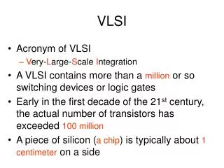
VLSI Team 5. 10/100 Ethernet MAC. http://code.google.com/p/inf-vlsi-group5-spring2013/ Chatziioannou Dimitris Delivos Giannis Katsiris Giannis. Project Architecture Overview. Wishbone Bus. Wishbone: A SoC interconnect standard for fostering design re-use Features:

VLSI Team 5
E N D
Presentation Transcript
VLSI Team 5 10/100 Ethernet MAC http://code.google.com/p/inf-vlsi-group5-spring2013/ Chatziioannou Dimitris Delivos Giannis Katsiris Giannis
Wishbone Bus Wishbone: A SoC interconnect standard for fostering design re-use Features: Open specification, Patent & Royalty free On-Off chip architecture Point-to-point, shared bus, crossbar switch and switched fabric interconnections 64 bit address space, 8-64 bit data bus width (easily expandable) Handshaking protocol allows data transfer throttling Supports single read and write cycles Synchronous, all signals are triggered on the rising edge of the clock
Wishbone Common Signals CLK_I: Clock input, which coordinates all activities within the Wishbone interconnect. DAT_I(): The data input array. DAT_O(): The data output array. RST_I: Forces the Wishbone interface to restart. All internal state machines will be forced into an initial state. TGD_I(): Data tag type input. Contains information about the data in the input array. (parity protection, error correction etc.) TGD_O(): Data tag type output. Contains information about the data in the output array.
Wishbone Master Signals ACK_I: The acknowledge input. When asserted, indicates the normal termination of a bus cycle. ADR_O(): Used to pass a binary address. CYC_O: When asserted indicates that a valid bus cycle is in progress. Is asserted during the first data transfer and remains asserted until the last one. SEL_O(): Indicated whether valid data is expected on the DAT_I() / DAT_O() signal in read/write cycles. STB_O: Indicates a valid data transfer cycle. WE_O: Indictes whether the current local bus cycle is a read/write cycle.
Wishbone Slave Signals ACK_O: Indicates, when asserted, the termination of a normal bus cycle. ADR_I(): Used to pass a binary address. CYC_I: When asserted indicates that a valid bus cycle is in progress. Is asserted during the first data transfer and remains asserted until the last one. SEL_I(): Indicated whether valid data is expected on the DAT_I() / DAT_O() signal in read/write cycles. STB_I: Indicates a valid data transfer cycle. WE_I: Indictes whether the current local bus cycle is a read/write cycle.
Wishbone: Reset Operation All hardware interfaces are initialized to a pre-defined state. This is accomplished with the reset signal RST_O that can be asserted at any time. The reset signal RST_O is driven by the SYSCON module. It is connected to the RST_I signal on all MASTER and SLAVE interfaces. The reset signal RST_O can be extended for any length of time.
Wishbone: Handshake Protocol All bus cycles use a handshaking protocol between the Master and Slave interfaces. Master asserts STB_O when it's ready to transfer data. STB_O remains asserted until the Slave asserts one of the cycle terminating signals (ACK_I, ERR_I, RTY_I). The terminating signal is sampled at every rising clock edge, if it's asserted, STB_O is negated. This gives both Master and Slave interfaces the possibility control the rate at which data is transfered.
Wishbone: Single Read Cycle Clock edge 0: Master presents a valid address on ADR_O() and TGA_O(). Master negates WE_O to indicate a Read cycle. Master presents bank select SEL_O() to indicate where it expects data. Master asserts CYC_O and TGC_O() to indicate the start of the cycle and STB_O to indicate the start of the phase. Clock edge 1: Slave presents valid data on DAT_I() and TGD_I(). Slave asserts ACK_I in response to STB_O to indicate valid data. Note that Slave may insert any number of wait states before asserting ACK_I, allowing it to throttle data transfer speed. When ACK_I is asserted by the Slave, Master latches data on DAT_I() and TGD_I(). Master negates STB_O / CYC_O to indicate the end of the cycle. Slave nagates ACK_I in response to the negated STB_O.
Wishbone: Single Write Cycle Clock edge 0: Master presents a valid address on ADR_O() and TGA_O(). Master presents valid data on DAT_O() and TGD_O(). Master asserts WE_O to indicate a Write cycle. Master presents bank select SEL_O() to indicate where it sends data. Master asserts CYC_O and TGC_O() to indicate the start of the cycle and STB_O to indicate the start of the phase. Clock edge 1: Slave prepares to latch data on DAT_O() and TGD_O(). Slave asserts ACK_I in response to STB_O to indicate latched data. Note that Slave may insert any number of wait states before asserting ACK_I, allowing it to throttle data transfer speed. Slave latches data on DAT_O() and TGD_O(). Master negates STB_O / CYC_O to indicate the end of the cycle. Slave nagates ACK_I in response to the negated STB_O.
Wishbone: Timings The Wishbone specification is designed to provide the end user with very simple timing constraints. Although the application specific circuit(s) will vary in this regard, the interface itself is designed to work without the need for detailed timing specifications. In all cases, the only timing information that is needed by the end user is the maximum clock frequency (for CLK_I) that is passed to a place & route tool. The maximum clock frequency is dictated by the time delay between a positive clock edge on CLK_I to the setup on a stage further down the logical signal path. This delay is defined as Tpd,clk-su.
Ethernet Overview History Developed by Bob Metcalfe and others at Xerox PARC in mid-1970s. Standardized by Xerox, DEC, and Intel in 1978 LAN standards define MAC and physical layer connectivity IEEE 802.3 (CSMA/CD - Ethernet) standard – originally 2Mbps IEEE 802.3u standard for 100Mbps Ethernet IEEE 802.3z standard for 1,000Mbps Ethernet CSMA/CD: Ethernet’s Media Access Control (MAC) policy – CS = carrier sense Send only if medium is idle MA = multiple access CD = collision detection Stop sending immediately if collision is detected 802.3 standard defines both MAC and physical layer details
Ethernet Overview Ethernet by definition is a broadcast protocol Any signal can be received by all hosts Switching enables individual hosts to communicate Network layer packets are transmitted over an Ethernet by encapsulating in frames Frame format (sizes in octets)
Ethernet Frames Preamble is a sequence of 7 bytes, each set to “10101010” Used to synchronize receiver before actual data is sent Addresses unique, 48-bit unicast address assigned to each adapter example: 8:0:e4:b1:2 Each manufacturer gets their own address range broadcast: all 1s multicast: first bit is 1 Type field is a demultiplexing key used to determine which higher level protocol the frame should be delivered to Body can contain up to 1500 bytes of data Maximum 1500 bytes (= 05DCh)
Ethernet's MAC MAC: Media Access Control Ethernet uses CSMA/CD – listens to line before/during sending If line is idle (no carrier sensed) Send packet immediately Upper bound message size of 1500 bytes Must wait 9.6 μs between back-to-back frames If line is busy (carrier sensed) Wait until idle and transmit immediately Called 1-persistent sending If collision detected Stop sending and jam signal Try again later
Ethernet's MAC Senders handle all access control Receivers simply read frames with acceptable address Address to host Address to broadcast Address to multicast to which host belongs All frames if host is in promiscuous mode Frame CRC (CRC32) sent by sender, is checked at the receiver side. If CRC does not match, then frame is discarded.
Modules' Overview TX and RX Module Τhe TX and RX modules provide full transmit and receive functionality. CRC generators are incorporated in both modules for error detection purposes.. The modules also handle preamble generation and removal. Padding occurs automatically (when enabled) in compliance with the IEEE 802.3 standard. When enabled, packets greater than the standard can be transmitted. Control Module The control module provides full duplex flow control, according to the IEEE 802.3u standard. Flow control is achieved by transfering the PAUSE control frames between thecommunicating stations. Management Module (MIIM) The management module provides the standard IEEE 802.3 Media Independent Interface (MII) that defines the connection between the PHY and link layers. Using this interface, the device connected to the host interface can force PHY to run at 10Mbps versus 100Mbps or to configure it to run at full versus half duplex mode.
RX Module The Receive module consists of four sub modules: eth_crc – Cyclic Redundancy Check (CRC) module eth_rxaddrcheck – Address recognition module eth_rxcounters – Various counters needed for packet reception eth_rxstatem – State machine for Receive module
ΤΧ Module The Transmit module consists of four sub modules: eth_crc – Cyclic Redundancy Check (CRC) module generates 32-bit CRC that is appended to the data field. eth_random – Generates random delay that is needed when back off is performed (after the collision) eth_txcounters – Various counters needed for packet transmission eth_txstatem – State machine for TX module
Wishbone Module Module has multiple functions: It is the interface between the Ethernet Core and other devices (memory, host). Two Wishbone interfaces (slave and master) are used for this manner. Contains buffer descriptors (in the internal RAM). Contains receive and transmit FIFO. Contains synchronization logic for signals that spread through different clock domains. Transmit related function that reads TX BD and then starts Wishbone master interface, fills the TX FIFO and then starts the transmission. At the end it writes status to the related TX BD. Receive related function that reads RX BD, assembles incoming bytes to words and then writes them to the RX FIFO. They are then written to the memory through the Wishbone master interface. At the end it writes status to the related RX BD.
Wishbone Module Wishbone Master Interface The ethernet core uses the master interface for accessing the memory where the buffers are stored. Both the receiver and the transmitter use the same wishbone interface Wishbone Slave Interface Ethernet core's registers are all accessed through the Slave Wishbone interface. Registers are located in the registers' module while BDs are saved in eth_wishbone module's internal RAM.
Testbench: Memory/BD Clear Writing 0x0 starting from address base + offset (base is 0xd0000000) TX buffer descriptors are at 0xd0000400 RX buffer descriptors are at 0xd0000600
Testbench: Register access/testing Writing and reading back, 0xffffffff to ETH_MAC_ADDR0 register ETH_MAC_ADDR0 address is at 0xd0000000 + 0x40
DesignCompiler Commands analyze -format verilog { <Verilog files> } elaborate ethmac -architecture verilog -library DEFAULT create_clock -name "wbclk" -period 15 -waveform { 1 2 } { wb_clk_i } create_clock -name "rxclk" -period 20 -waveform { 1 2 } { mrx_clk_pad_i } create_clock -name "txclk" -period 20 -waveform { 1 2 } { mtx_clk_pad_i } set_dont_touch_network wbclk set_dont_touch_network txclk set_dont_touch_network rxclk set_clock_transition 0.1 wbclk set_clock_transition 0.1 txclk set_clock_transition 0.1 rxclk set_clock_uncertainty 0.1 wbclk set_clock_uncertainty 0.1 txclk set_clock_uncertainty 0.1 rxclk write -hierarchy -format ddc compile -exact_map -map_effort high -area_effort none -power_effort high
Compilation Results http://inf-vlsi-group5-spring2013.googlecode.com/hg/logs/compile_log
Routing with Cadence Encounter 112 modules 50377 stdCells 5 Metal layers Total wire length on LAYER metal1 = 156 um. Total wire length on LAYER metal2 = 606928 um. Total wire length on LAYER metal3 = 947712 um. Total wire length on LAYER metal4 = 865193 um. Total wire length on LAYER metal5 = 482034 um. Total wire length on LAYER metal6 = 14580 um. Total number of vias: 241659