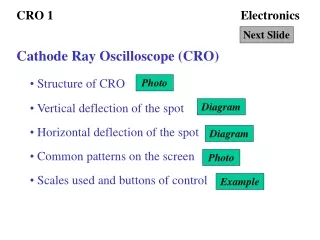
Electronics
Electronics. Involves the use of devices and circuits to control the flow of electric current to achieve some purpose. These circuits contain: Resistors, capacitors, inductors… Electronic devices: diodes, transistors (non-linear devices)… These devices are termed solid state . Power.

Electronics
E N D
Presentation Transcript
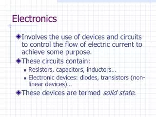
Electronics • Involves the use of devices and circuits to control the flow of electric current to achieve some purpose. • These circuits contain: • Resistors, capacitors, inductors… • Electronic devices: diodes, transistors (non-linear devices)… • These devices are termed solid state.
Power • The transfer of power from its generation point to its point of use may be done by using: • AC – alternating current. • DC – Direct current. • Most electronic circuit require DC as a source of power in order to operate.
Analog and Digital Systems • Signal – a voltage or current varied over time in order to encode and transmit information. • Electronic systems may be classified by the type of signal they process. • Analog. • Digital.
Analog Signals • Signals that vary continuously with time.
Analog Systems • This systems handle analog signals and these signals may be complex or periodic. Note that a complex signal can be shown to be composed of a number of sinusoidal signals.
Sinusoidally Varying Signals • v(t) = A sin(ωt + θ) • A = amplitude. • ω = angular frequency (radians per second). • Θ = phase angle. • Frequency in Hertz is given by the following relation: • f = ω/2∏
Digital Signals • Signals that switch between discrete levels over time.
Pulses • Classified as: • Positive. • Negative.
Serial and Parallel • The transmission of information may be classified as: • Serial – when the information is transmitted over a single line. • Parallel – when the information is transmitted over several lines simultaneously.
Amplifiers and Gain • Amplifiers are electronic circuit used to increase the amplitude of signal. This signal may be a voltage or current. • The gain of a voltage amplifier is determined by the following ratio:
Decibels • The gain of an amplifier is sometimes expressed in decibels (db), which is defined by:
Frequency Response • The way in which the gain varies as the frequency of a sinusoidal input signal is changed.
Half-power Frequencies • The high and low frequencies where the gain is reduced by a factor of .707 from the midband value are termed: • fLO - low-corner frequency. • fHI - upper-corner frequency. • These are the half power frequencies.
Bandwidth • The difference in frequency between the upper-corner frequency and the lower-corner frequency.
Modulation and Demodulation • Modulation is the process used to encode information on an analog signal. • Demodulation is the process used to extract information from an analog signal. • Modem – modulator-demodulator.
Modulation and Demodulation • A signal may be encoded with: • Amplitude modulation; • Frequency modulation; • Phase modulation
Amplitude Modulation • In amplitude modulation the amplitude of the carrier wave is changed by the information to be transmitted.
Upper and Lower Sidebands • The previous result showed that the amplitude modulation had a frequency component at the carrier frequency and two components with the information at the (ωc + ωm) and (ωc - ωm) frequencies. These are called the upper and lower sidebands.
Encoding and Decoding • Encoding is the process used to encode information on a digital signal. • Decoding is the process used to extract information from a digital signal.
Digital Systems • Digital systems use circuits with binary logic which are represented by voltages ,and sometimes currents, that switch between one of two possible levels. • These level are called: • Logic 0 – low level; • Logic 1 – high level. • A bit, binary digit, is a single unit of digital information.
Digital Systems • A series of bit that represent some information is termed a digital word. • Nibble = 4 bits; • Byte = 8 bits; • Word = 16 bits; • Double word = 32 bits; • Quad word = 64 bits.
Digitizing Analog Signals • This is the process of converting an analog signal into a digital one. • An analog signal varies continuously over time while a digital signal varies at discrete points in time.
Digitizing Analog Signals • Sampling Rate: • Number of times the signal is sampled each second. • Minimum sampling rate, also known as the Nyquist frequency, is twice the maximum frequency of the signal being sampled.
Digitizing Analog Signals • Resolution is the number of zones for quantization. The number of bits each sample will be represent with. • Z = 2n where n is the number of bits.
Logic Gates • Most basic digital device. • Electronic circuits that has one or more inputs that accept voltage level corresponding to logic 0 and logic 1 signals and produce an output that is a function of the current input values. • Any digital function can be realized with just three types of gates, the AND, OR and NOT gates.
Logic Gates • AND gate • OR Gate • Inverter