PCBA Cleanliness Guidelines
PCBA Cleanliness Guidelines. Dr. Craig D. Hillman. Outline. PCBA cleaning process details Cleanliness specifications & test methods Ionic contamination: acceptance levels Recommended fluxes and platings Product qualification guidelines Sources of contamination.

PCBA Cleanliness Guidelines
E N D
Presentation Transcript
PCBA Cleanliness Guidelines Dr. Craig D. Hillman
Outline • PCBA cleaning process details • Cleanliness specifications & test methods • Ionic contamination: acceptance levels • Recommended fluxes and platings • Product qualification guidelines • Sources of contamination
Best Practices: Control & Measure • Confirm incoming board cleanliness • Clean before solder mask application • Clean after soldering operations • Then measure: • Water quality going into process • Assembly cleanliness with ionograph
PCBA Cleanliness: Overview • Ensuring the cleanliness of printed circuit board assemblies involves process and control • Process • Cleaning must introduced at the appropriate locations within the manufacturing process • Control • The effectiveness of the cleaning processes must be validated through monitoring and measurement
Printed Circuit Board Cleanliness • The cleanliness of printed circuit boards (PCBs) has become especially critical in recent years due to • Decreasing conductor spacings (increased risk of electrochemical migration) • Increased use of no-clean flux (the last cleaning operations are PCB fabrication) • Movement of PCB fabrication to low cost countries
PCB Cleaning: Process Flow • At a minimum, PCB manufacturers should clean the PCB: • Immediately before the application of solder resist • Immediately after the application of any solderability plating • HASL • Electroless Nickel and Immersion Gold • Immersion Tin • Immersion Silver • Some PCB manufacturers also perform a final clean • Should not substitute cleaning after solderability plating • Residues from plating operations can become more difficult to remove with any time delay
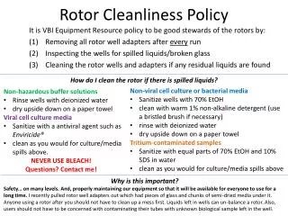
PCB Cleaning Process: Requirements • Final rinse with deionized (DI) water • 18 MW is preferred • Distilled water is insufficient • ‘City’ water is unacceptable • Potential options • Use of saponifier during the cleaning process • Heated DI water is nice, but not absolutely necessary • Common problems • DI water is only used if specified by the customer • DI water is turned off to reduce water and energy usage • Failure to monitor DI water at the source • Failure to alarm the DI water on the manufacturing floor
PCB Cleanliness Control: Industry Specs • IPC-6012B, Qualification and Performance Specification for Rigid Printed Boards, Section 3.9 • Requires confirmation of board cleanliness before solder resist application • When specified, requires confirmation of board cleanliness after solder resist or solderability plating • Board cleanliness before solder resist shall not be greater than 10 ug/in2 of NaCl equivalent (total ionics) • Based on military specifications from >30 years ago • Board cleanliness after solder resist shall meet the requirements specified by the customer
PCB Cleanliness Control: Test Procedures • IPC-6012B specifies a Resistance of Solvent Extract (ROSE) method • Defined by IPC-TM-650 2.3.25 • IPC-6012B specifies this measurement should be performed on production boards every lot • Class 1 boards: Sampling Plan 6.5 • Class 2 and 3 boards: Sample Plan 4.0 • Sampling plan (example) • If a lot contains 500 panels of a Class 2 product, 11 panels should be subjected to ROSE measurements for cleanliness testing
ROSE is the least sensitive of ionic measurement techniques 5 ug/in2 detected by ROSE is equivalent to ~20 ug/in2 detected by ion chromatography Equipment is not calibrated Insufficient volume of solution is used Insufficient surface area Panels are preferred over single boards Cut-outs are not considered when calculating surface area Insufficient measurement time 7 to 10 minutes is preferred Test Procedures: Common Problems
Test Procedures: Best Practice • Ion Chromatography (IC) is the ‘gold standard’ • Some, but very few, PCB manufacturers qualify lots based on IC results • Larger group uses IC to baseline ROSE / Omegameter / Ionograph (R/O/I) results • Perform lot qualification with R/O/I • Periodically recalibrate with IC (every week, month, or quarter)
PCB Cleanliness Control: Requirements • The majority of knowledgeable OEMs completely ignore IPC cleanliness requirements • Option 1: Requirements are based on R/O/I test results, but adjusted for lack of sensitivity • Most companies now specify 2.5 to 7 ug/in2 • Option 2: Requirements are based on IC test results and then monitored using R/O/I
Cleanliness Controls: Ion Chromatography • Contamination tends to be controlled through industrial specifications (IPC-6012, J-STD-001) • Primarily based on original military specification • 10 mg/in2 of NaCl ‘equivalent’ • Calculated to result in 2 megaohm surface insulation resistance (SIR) • Not necessarily best practice • Best practice is contamination controlled through ion chromatography (IC) testing • IPC-TM-650, Method 2.3.28A *Based on R/O/I testing
DfR Solutions IC Requirements • Fluorides < 1 mg/in2 • Chlorides < 2 mg/in2 • Bromides < 10 mg/in2 • Nitrates, Sulfates < 2 – 4 mg/in2 • WOAs < 175 mg/in2 • Note: WOA spec may not be necessary depending upon flux used for HASL process
Best Practices: Application Specific • Indoor applications: controlled environment • Use of no-clean fluxes often sufficient (see caveats) • Outdoor applications: uncontrolled • Non-condensing (ex: telecom): • Use of more aggressive cleaning of boards rather than no-clean flux • Condensing (ex: military): • Use of conformal coatings
Best Practices: Use of No-Clean Flux • Generally good at eliminating assembly-induced contamination • Caveats: • Places a larger emphasis on cleaning of incoming boards • Wave soldering and/or rework may result in: • Pooling of flux: heterogeneous contamination issues • Flux not being deactivated: resulting acids may cause oxidation and electro-chemical migration • Surface mount reflow rarely has such issues
Flux Controls • Strong movement to no-halide, no-clean flux • How to ensure flux choice does not induce ECM? • Option 1: Attempt to characterize flux chemistry • Limited published literature • Option 2: Qualify the flux through testing • Requires test vehicle
Flux Qualification • Test vehicle requirements • Fabricated from same material as production unit (board and solder mask) • Minimum of two structures • Smallest spacing at relevant voltage • Highest electric field at relevant spacing • Clean test vehicle before use • Designed to assess flux/solder mask interaction (not board contamination)
Recommended Test Method • Flux application and preconditioning • Solder paste • Wave solder • Rework • Exposure to low temperature and maximum humidity without condensation • 35 to 40ºC • Minimum of 93%RH • 72 to 120 hours of exposure • Continuous monitoring (1 second per reading)
Product Qualification • Consider testing entire product, if resource- or time-limited • 40ºC/93%RH for 72 to 120 hours • Extend time period if using conformal coating or potting material • Do not test at 85ºC/85%RH for dendritic growth (surface ECM) • Some issues with CAF as well • Study by Sohm and Ray (Bell Labs) demonstrated degradation of weak organic acid residues above ~55ºC • Reduces their effect on surface insulation resistance • Turbini (Georgia Tech) demonstrated breakdown of polyglycols at elevated temperature as well • Absorption into board can increase risk of CAF
Contamination: Sources • Handling and storage • Fingerprints: NaCl and organic acids • Dust from environment and packaging: ionic materials • Use environment • Forced air circulation is a significant source • Gaseous: HCl and chlorine • Particulates (most significant): • Coarse (>1um): sulfate, ammonium, Ca, Mg, Na, Cl • Fine: sulfate & ammonium – careful filtration required
Contamination: Sources • Rework and Repair • High rework temperatures cause decomposition of board materials and fluxes • Cleaning methods typically not as good as in-line processes
Plating Recommendations • Except for immersion silver, selection of PCB plating material should be independent of use environment • Immersion silver has a tendency to corrode in high sulfur environments, creating electrical shorts
RoHS Cleanliness • The cleanliness guidelines spelled out in this document, in regards to process and control, are not expected to change with the transition to a RoHS-compliant product • Caveat: If the PCBA is cleaned, cleaning procedures may need to be modified
Transition to No-Clean Flux • The primary consideration in the transition to no-clean flux in regards to cleanliness is the additional focus on ensuring the PCB cleaning process is effective and controlled
Any questions? • Dr. Craig Hillman: chillman@dfrsolutions.com, 301-474-0607 (Main Office)