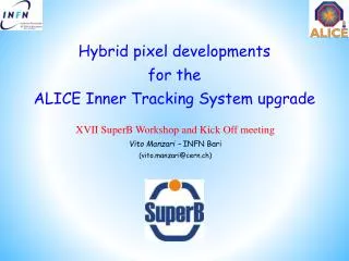
Hybrid pixel developments for the ALICE Inner Tracking System upgrade
410 likes | 693 Vues
Hybrid pixel developments for the ALICE Inner Tracking System upgrade XVII SuperB Workshop and Kick Off meeting Vito Manzari – INFN Bari ( vito.manzari@cern.ch ). Outline. Introduction ITS upgrade Hybrid Pixel R&D activities : Thin planar sensor

Hybrid pixel developments for the ALICE Inner Tracking System upgrade
E N D
Presentation Transcript
Hybrid pixel developments for the ALICE Inner Tracking System upgrade XVII SuperB Workshop and Kick Off meeting Vito Manzari – INFN Bari (vito.manzari@cern.ch)
Outline • Introduction • ITS upgrade • HybridPixel R&D activities: • Thinplanar sensor • Thinactiveedge planar sensor • Front-end chip thinning • PolyimideMicroChannelcooling • Conclusions XVII SuperB Workshop and Kick Off meeting– 29 May 2011
The ALICE experiment • Ultra-relativistic nucleus-nucleus collisions • study behavior of strongly interacting matter under extreme conditions of compression and heat • Proton-Proton collisions • reference data for heavy-ion program • unique physics (momentum cutoff <100MeV/c, excellent PID, efficient minimum bias trigger) Size: 16 x 26 meters Weight: 10,000 tonnes XVII SuperB Workshop and Kick Off meeting– 29 May 2011
The ALICE Inner Tracking System • 6-layer barrel • 3 different silicon detector technologies, 2 layers each (inner outer): • - Pixels (SPD), Drift (SDD), double-side Strips (SSD) Size: 16 x 26 meters Weight: 10,000 tonnes XVII SuperB Workshop and Kick Off meeting– 29 May 2011
The ALICE Inner Tracking System XVII SuperB Workshop and Kick Off meeting– 29 May 2011
Pb-Pb event XVII SuperB Workshop and Kick Off meeting– 29 May 2011
ALICE ITS Upgrade • Aims to extend the ALICE physics capabilities for the identification of short-lived particles containing heavy quarks through reconstruction and identification of the displaced vertex at mid-rapidity and enlarge the acceptance to larger rapidity • Improve the impact parameter resolution to ≈50 μm up to very low pT • Get closer to the Interaction Point • Radius of the innermost PIXEL layer < 25mm (at present 39mm) • reduce beam pipe radius to 20mm (at present 29mm) • Reduce material budget, especially innermost layers (at present ≈1.1% X0) • Reduce mass of silicon, power and signals bus, cooling, mechanics • Monolithic Pixels • Reduce pixel size, mainly for medium/high pT (at present 50μm x 425μm) • Improve standalone tracking and PID capabilities • Improve readout and trigger capabilities • Acceptance at Forward and Backward rapidity • Exchange/replacement capability and spatial mapping XVII SuperB Workshop and Kick Off meeting– 29 May 2011
Basic idea of the Pixel Barrel 3 Si-pixel Layers Carbon Fiber skin Cooling tubes Carbon fiber support wheel • 3 layers of Si-pixel detectors • As close as possible to the interaction • beam pipe radius = 20mm • innermost average radius = 23mm • Low material budget (< 0.5% X0) • Acceptance |η| = 1 • Power consumption < 0.5 W/cm2 • several cooling options • All services from one side • fast extraction (winter shutdown) for fixing XVII SuperB Workshop and Kick Off meeting– 29 May 2011
Basic idea of the Pixel Barrel Innermost layer cross-section Inlet / outlet Cooling tube Carbon fiber support skin Single module cross-section Carbon foam Pixel detector XVII SuperB Workshop and Kick Off meeting– 29 May 2011
Pixel Detector R&D • Two main technologies are being evaluated for the Pixel Barrel: • Monolithic pixel detectors • MIMOSA, INMAPS, LePix • Lower material budget and larger area (low cost) • radiation tolerance and readout speed to be evaluated • Hybrid pixel detectors • “State-of-the-art” of pixel detectors at LHC • R&D • Material budget • thinning of the silicon substrates: sensor and front-end chip • reduce overlaps between modules: active edge, 3D • multilayer flex and cooling • Low cost bump-bonding • Low power FEE chip XVII SuperB Workshop and Kick Off meeting– 29 May 2011
13.5 mm 15.8 mm ALICE Pixel Overview 5 Al layer bus + extender • 2 layer barrel • Total surface: ~0.24m2 • Power consumption ~1.5kW • Evaporative cooling C4F10 • Room temperature • Material budget per layer ~1% X0 MCM + extender + 3 fiber link Ladder 1 Ladder 2 MCM Grounding foil Half-stave Outer surface: 80 half-staves • ALICELHCb1 • readout chip • mixed signals • 8192 cells • 50x425mm2 ~1200 wire-bonds • Unique L0 trigger capability • Prompt FastOR signal in each chip • Extract and synchronize 1200 FastOR signals from the 120 half-staves • User defined programmable algorithms Inner surface: 40 half-staves XVII SuperB Workshop and Kick Off meeting– 29 May 2011
ALICE Pixel Overview • The Silicon Pixel Detector was installed in ALICE in Jun‘07 Inner layer Beam pipe Outer layer Minimum distance inner layer-beam pipe 5 mm XVII SuperB Workshop and Kick Off meeting– 29 May 2011
ALICE Pixel Material Budget • Contributions to one current Pixel layer • Carbon fiber support: 200 μm • Cooling tube (Phynox): 40 μmwall thickness • Grounding foil (Al-Kapton): 75 μm • Silicon pixel chip: 150 μm 0.16% X0 • Bump bonds (Pb-Sn): diameter ~15-20 μm • Silicon sensor: 200 μm 0.22% X0 • Multilayer Al/Kapton pixel bus: 280 μm 0.48% X0 • SMD components • Glue (Eccobond 45) and thermal grease Two main contributors: siliconand multilayer flex (pixel bus) XVII SuperB Workshop and Kick Off meeting– 29 May 2011
Hybrid Pixel R&D: Material Budget • How can the material budget be reduced? • Reduce silicon front-end chip thickness • Reduce silicon sensor thickness • Reduce interconnect bus contribution • - reduce power • Reduce edge dead regions on sensor • - reduce overlaps to avoid gaps • Review also other components • - average contribution ~0.02% • What can be a reasonable target • Hybrid pixels overall material budget: 0.5 % X0 • silicon: 0.16%X0overall (100μm sensor + 50μm front end chip), at present 0.38% • bus: 0.24%X0, at present 0.48% • others: 0.1% X0overall, at present 0.24% • Monolithic pixels: 0.3÷0.4%X0 (e.g. STAR HFT) XVII SuperB Workshop and Kick Off meeting– 29 May 2011
Hybrid Pixel R&D: Material Budget • To reduce the silicon contribution to the overall material budget Threefold activity • Thin Planar Sensor based on the current ALICE layout • bump-bonded to present ALICE front-end chip for testing • Thin Planar Active Edge Sensor based on the current ALICE layout • bump-bonded to present ALICE front-end chip for testing • Thinning the existing ALICE front-end chip • Bump-bonded to standard ALICE sensor 200 μmthick for testing • And then combine them XVII SuperB Workshop and Kick Off meeting– 29 May 2011
Hybrid Pixel R&D: Thin Planar Sensor • Procurement, Processing and Handling of ≈100μm thick wafers is an issue • Alternative: Epitaxial Wafers to be thinned during the bump-bonding process • Epitaxial wafers provide a mean to use very thin sensor wafers • carrier wafer “included for free” • First tests of epitaxial sensors by PANDA (D. Calvo et al.) [see NIM A 595(2008)] • ALICE Epi-Pixel sensor • Goal: achieve a sensor thickness of 100 μm (~ 0.11% X0) • Test with the ALICE pixel front-end chip (optimized for 200μm sensor) • Epitaxial wafers produced by ITME (Poland) • Substrate thickness 525μm, doping n/Sb, resistivity 0.008-0.02 Ωcm, <111> • Epitaxial layer thickness 95-105μm, doping n/P, resistivity 2000±100 Ωcm XVII SuperB Workshop and Kick Off meeting– 29 May 2011
ALICE Epi-Pixel Sensor • 5 sensor wafers fabricated at FBK • 3 wafers processed at VTT • successfully through all process steps, including thinning and back side patterning • Overall thickness: 105-115 μm(i.e. epilayer + ≈10 μm) • 5 singles flip-chip bonded to the current ALICE pixel front-end chip • electrical tests: ~30 nA at 20V at RT, min. threshold ~ 1500 el., ~30 missing pixels XVII SuperB Workshop and Kick Off meeting– 29 May 2011
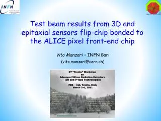
Beam Test of Epi-Pixel detector • Beam test of ALICE Epi-Pixel detector • November 2010 • CERN SPS: positive beam (pions, protons), 350 GeV/c, up to 104 particles/spill • Duty cicle 49s, Flat top ≈ 9s, Trigger rate ≈3KHz • ALICE 3D-Pixel detector samples were also tested • Double-sided Double-Type Column (DDTC) from FBK multi-project wafer • Tracking Telescope • 4 ALICE standard Pixel detector arranged in 2 stations • each station contains 2 pixel detectors arranged in cross-geometry • pixel cell dimensions 50 x 425 μm2 • Estimated tracking precision ≈10µm both in x and y directions • Trigger • Self-triggering: FastOr logic combining the information from the tracking planes XVII SuperB Workshop and Kick Off meeting– 29 May 2011
Beam Test Set-up Single assembly mounted on test card SPS beam test set-up XVII SuperB Workshop and Kick Off meeting– 29 May 2011
Beam Test Measurements • Track Efficiency • Cluster size • Space accuracy • Depletion Voltage • Threshold • Particle Crossing Angle vs Objectives Online beam spot Tracking Station 1 3D-sensor Epi-sensor Tracking Station 2 XVII SuperB Workshop and Kick Off meeting– 29 May 2011
Residuals and Efficiency ALICE SPD • NIM paper in preparation XVII SuperB Workshop and Kick Off meeting– 29 May 2011
Planar Pixel Sensor with Active Edge • Standard detectors • Dead region (cracks and damages) a + d ≥500 μm • Active edge to limit dead region • Cut lines not sawed but etched with Deep Reactive Ion Etching (DRIE) and doped Standard Detector Active Edge Detector • R&D in collaboration with FBK • Within the MEMS2 agreement FBK-INFN • Epitaxial wafer in order to achieve an Active Edge 100μm thick Planar Sensor XVII SuperB Workshop and Kick Off meeting– 29 May 2011
Active Edge Detector • Main process steps and critical issues • Attach support wafer • provides mechanical support after trench etching (SOI, wafer bonding, … ) • Trench opening by Deep Reactive Ion Etching (DRIE) • dimensional aspect 1/20, deep etching (200-230 μm) • Inside trench doping • solid source technology • Trench filling with polysilicon • spin coating with standard photoresist is challenging due to trench • Remove devices from support wafers (after bumping in case of pixel sensors) XVII SuperB Workshop and Kick Off meeting– 29 May 2011
Active Edge Detector XVII SuperB Workshop and Kick Off meeting– 29 May 2011
Active Edge Detector XVII SuperB Workshop and Kick Off meeting– 29 May 2011
Active Edge Detector XVII SuperB Workshop and Kick Off meeting– 29 May 2011
Active Edge Detector XVII SuperB Workshop and Kick Off meeting– 29 May 2011
ALICE Pixel with Active Edge • RecallALICE Epi-Pixel detector • Planar pixel sensor on epitaxial high resistivity silicon wafer • Remove the bulk by back-grinding after the bumping to achieve a 100 μm thick sensor • Combine with the capability to etch a trench to achieve an Active Edge Thinpixel detector Scribe Line Trench XVII SuperB Workshop and Kick Off meeting– 29 May 2011
ALICE Pixel with Active Edge XVII SuperB Workshop and Kick Off meeting– 29 May 2011
Front-end Chip Thinning • Current ALICE chips: 150 μm thinned during bump bonding process • Thickness reduction will make inherent stresses come out stronger • First experience during the ALICE production • Thinning process needs to be well studied and tuned to produce coherent results S. Vahanen, VTT XVII SuperB Workshop and Kick Off meeting– 29 May 2011
Front-end Chip Thinning R&D • Study using dummy components with IZM Berlin • Hybrid detector dummy components, i.e sensors and chips, based on ALICE layout • Specific IZM process for thinning: • Glass support wafer during full process • Laser release of the support wafer • Sensor wafers (200 μm) in processing, ASIC wafers ready in 4 weeks • First components back by end July 2011 XVII SuperB Workshop and Kick Off meeting– 29 May 2011
Front-end Chip Thinning R&D XVII SuperB Workshop and Kick Off meeting– 29 May 2011
Front-end Chip Thinning R&D XVII SuperB Workshop and Kick Off meeting– 29 May 2011
Front-end Chip Thinning R&D XVII SuperB Workshop and Kick Off meeting– 29 May 2011
Polyimide MicroChannel cooling SMD COMP 5 4 3 2 1 SENSOR READOUT CHIP SMD COMP Pyralux® LF7001 (Kapton®) 24µm Pyralux® PC 1020 (polyimide) 200µm 5 4 3 2 1 Pyralux® LF110 (Kapton®) 50µm SENSOR Wtot = 1.6 cm OUT READOUT CHIP CARBONFIBER SUPPORT q = 0.4 W/cm2 COOLING TUBE Ltot = 20 cm IN XVII SuperB Workshop and Kick Off meeting– 29 May 2011
T water out 18°C L = 20 cm W= 1.6 cm T water in 15°C OUT IN MicroChannel Simulation (Fluent 6.2) • Assuming • ΔTmax = 3°C • Leakless (underpressure) system Top Layer 16 channels 800 x 200 µm2 T water out 18°C T water in 15°C 16.65 °C 20.62 °C Axonometric view of a single channel Inletsection Outlet section Middle section XVII SuperB Workshop and Kick Off meeting– 29 May 2011
MicroChannel Production Pyralux® LF7001 (Kapton®) 24µm Pyralux® PC 1020 (polyimide) 200µm • Main fabrication process steps (R. De Oliveira, CERN TM-MPE-EM) • Sheet 50 µm of LF110 • Lamination 200 µm photoimageablecoverlay (4 layers of PC1020) • Creation of the grooves (800 x 200 µm2) • by photolithography process @ 180°C • Gluing by hot pressing the LF7001 24 µm lid • cured @ 180°C for 10h Pyralux® LF110 (Kapton®) 50µm XVII SuperB Workshop and Kick Off meeting– 29 May 2011
MicroChannel Material Budget % Xo 0.094 0.094 0.085 µm • Material budget of the ALICE Pixel cooling (Phynox tube + C4F10) ≈ O.8 % X0 Single channel Cross section 0 100 900 1000 XVII SuperB Workshop and Kick Off meeting– 29 May 2011
Conclusions • The ITS upgrade aims to increase the ALICE sensitivity to heavy flavour by improving the impact parameter resolution • Both Monolithic and Hybrid Pixels are being considered for the upgrade • At present, for the innermost layers the hybrid option seems to be preferable compared to the monolithic for radiation hardness • A very light (≤ 0.5 % X0) pixel detector is necessary • R&D activities ongoing: • thin active edge planar sensor • front-end chip thinning • polyimide microchannel cooling XVII SuperB Workshop and Kick Off meeting– 29 May 2011
Timeline • The upgrade should target the Phase I (2017-18) shutdown • The scope of the upgrade Phase I should be well tailored to what can be reasonably prepared and tested within the next five years and installed in 15 months. • The full upgrade program might require a two step approach with a partial upgrade in Phase I and the completion in Phase II (2020 and beyond) • Decisions on upgrade plans in terms of physics strategy, detector feasibility, funding availability, should be taken in 2011 • Expression of Interest: ready • Preparation of a technical proposal till summer 2011 • R&D for Phase I: 2010-2014 • Production and pre-commissioning for Phase I: 2014-2016 • Installation and commissioning for Phase I: 2017 XVII SuperB Workshop and Kick Off meeting– 29 May 2011