Download
1 / 35
350 likes | 538 Vues
Geometry baseline of the new Inner Tracking System, ALICE Chinorat Kobdaj Suranaree University of Technology, Thailand On behalf of the ALICE Collaboration Aug 8, 2013. The ALICE Detector. Introduction to the Inner Tracking System upgrade. The Current ALICE Detector.

E N D
Geometry baseline of the new Inner Tracking System, ALICE ChinoratKobdaj Suranaree University of Technology, Thailand On behalf of the ALICE Collaboration Aug 8, 2013 APCTP 2013 LHC Physics Workshop @ Korea, August 6-8, 2013, KonkukUniveristy, Seoul, South Korea
The ALICE Detector Introduction to the Inner Tracking System upgrade The Current ALICE Detector APCTP 2013 LHC Physics Workshop @ Korea, August 6-8, 2013, KonkukUniveristy, Seoul, South Korea
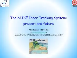
ALICE ITS (present detector) The Current ALICE Inner Tracking System ALICE ITS ALICE ITS • Current ITS • 6 concentric barrels, 3 different technologies • 2 layers of silicon pixel (SPD) • 2 layers of silicon drift (SDD) • 2 layers of silicon strips (SSD) ALICE ITS APCTP 2013 LHC Physics Workshop @ Korea, August 6-8, 2013, KonkukUniveristy, Seoul, South Korea
LoI and ITS CDR endorsed by LHCC in Sep 2012 APCTP 2013 LHC Physics Workshop @ Korea, August 6-8, 2013, KonkukUniveristy, Seoul, South Korea
ALICE ITS Upgrade 2021 Complete
Time Line Run Construction and Installation R &D Production/ Construction and Test of Detector modules Long Shutdown 3 Complete Evaluation Technology Long Shutdown 1 Long Shutdown 2 Pre-commissioning and Assembly Full deployment of DAQ/HLT Conceptual Design Report Technical Design Report Final Design and Validation Selection of Technologies Prototype Pb-Pb at √sNN= 5.1 TeV Installation in the cavern Pb-Pb Pb-Pb at √sNN = 5.5 TeV Ar-Ar high luminosity run p-Pb at full energy Today 2012 2013 2014 2015 2016 2017 2018 2019 2020 2021 2022 APCTP 2013 LHC Physics Workshop @ Korea, August 6-8, 2013, KonkukUniveristy, Seoul, South Korea
New ITS Design goals • 1. Improve impact parameter resolution by a factor of ~3 • Get closer to IP (position of first layer): 39mm 22mm • Reduce material budget: X/X0 /layer: ~1.14% ~ 0.3% • (for inner layers) • Reduce pixel size • currently 50mm x 425mm • monolithic pixels O(20mm x 20mm), • hybrid pixels state-of-the-art O(50mm x 50mm) APCTP 2013 LHC Physics Workshop @ Korea, August 6-8, 2013, KonkukUniveristy, Seoul, South Korea
2. Improve tracking efficiency and pT resolution at low pT • Increase granularity: 6 layers 7 layers , reduce pixel size • Increase radial extension: 39-430 mm 22– 430 (500) mm • 3. Fast readout • readout of Pb-Pb interactions at > 50 kHz and pp interactions at ~ several MHz • 4. Fast insertion/removal for yearly maintenance • possibility to replace non functioning detector modules during yearly shutdown APCTP 2013 LHC Physics Workshop @ Korea, August 6-8, 2013, KonkukUniveristy, Seoul, South Korea
Upgrade options Two design options have being studied 7 layers of pixel detectors (baseline) 3 inner layers of pixel detectors and 4 outer layers of strip detectors Option B 4 layers of strips Option A 7 layers of pixels 3 layers of pixels Pixels: O(20x20µm2 – 50 x 50µm2) Pixels: O( 20x20µm2 – 50 x 50µm2) Strips: 95 µm x 2 cm, double sided APCTP 2013 LHC Physics Workshop @ Korea, August 6-8, 2013, KonkukUniveristy, Seoul, South Korea
New ITS (baseline) • Inner Barrel: 3 layers • Outer Barrel: 4 layers • Detector module (Stave) consists of • Carbon fiber mechanical support • Cooling unit • Polyimide printed circuit board • Silicon chips (CMOS sensors) APCTP 2013 LHC Physics Workshop @ Korea, August 6-8, 2013, KonkukUniveristy, Seoul, South Korea
Inner Barrel Layers 3 innermost layers at r= 22, 28 and 36 mm Same z-length: 27 cm Assumed chip size: 15 mm x 30 mm >> 9 chips/module X/X0≤ 0.3% APCTP 2013 LHC Physics Workshop @ Korea, August 6-8, 2013, KonkukUniveristy, Seoul, South Korea
Middle and Outer Barrel Layers 12 APCTP 2013 LHC Physics Workshop @ Korea, August 6-8, 2013, Konkuk Univeristy, Seoul, South Korea 4 outermost layers at r= 48, 52, 96 and 102 mm 84 cm < z-length < 150 cm Double chip rows per module X/X0≤ 0.8%
PROJECT ORGANIZATION 1. Physics Performance 2. Detector Simulation and Reconstruction Institute Board (PL, DPL, SPL, TC, Team Leaders) 3. Pixel chip design 4. Sensor Post Processing and Mass test 5. Characterization and Qualification Project Coordination (PL, DPL, SPL, TC, RC, Upgrade Tasks Coordinators) UPGRADE 6. Inner Layers Module 7. Middle Layers Module 8. Outer Layers Module ITS Operation (RC, PL, DPL, SPL, TC, QAC, CC, experts) 9. Mechanics and Cooling 10.Readout Electronics APCTP 2013 LHC Physics Workshop @ Korea, August 6-8, 2013, KonkukUniveristy, Seoul, South Korea
Organization • Participating Institutes • CERN • China (Wuhan) • Czech Republic (Prague) • France IN2P3-CNRS (Strasbourg) • Italy INFN (Bari, Bologna, Cagliari, Catania, Frascati, Legnaro, Padova, Roma, Torino, Trieste) • Korea (Inha, Pusan, Yonsei) • Netherlands (Nikhef and Utrecht) • Pakistan (COMSATS) • Russia (St. Petersburg) • Slovakia (Kosice IEP) • Thailand (NakhonRatchasima SUT) • UK STFC (Daresbury, RAL), Univ. of Birmingham • Ukraine (Kharkov, Kiev) • USA (Berkeley) APCTP 2013 LHC Physics Workshop @ Korea, August 6-8, 2013, KonkukUniveristy, Seoul, South Korea
Upgraded beampipe- studies A-side Al section C- side Al section Central Be part APCTP 2013 LHC Physics Workshop @ Korea, August 6-8, 2013, KonkukUniveristy, Seoul, South Korea
The upgraded beampipe, drawing v4.0 APCTP 2013 LHC Physics Workshop @ Korea, August 6-8, 2013, KonkukUniveristy, Seoul, South Korea
Effect of Al-extension on A sideBackground visible in Central Barrel detectors MC without the beampipe MC with the beampipe New ITS PIPE Physics Background b) Entries vsRadius a) Entries in (x,y) plane Extract only the secondary vertices physics events to see only the contribution from the new beampipe APCTP 2013 LHC Physics Workshop @ Korea, August 6-8, 2013, KonkukUniveristy, Seoul, South Korea
A-side Al section C- side Al section APCTP 2013 LHC Physics Workshop @ Korea, August 6-8, 2013, KonkukUniveristy, Seoul, South Korea
Effect of Al-extension on A sideBackground visible in Central Barrel detectors MC settings: HiJing central PbPb, interaction diamond: 6 cm Secondary particles further out (>20cm) are clearly negligible ... Effect of Al-part (|z|>40cm) is negligible < 1 per event Secondary vertices versus z direction APCTP 2013 LHC Physics Workshop @ Korea, August 6-8, 2013, KonkukUniveristy, Seoul, South Korea
Studies: Impact of materials in forward direction Compares number of gamma conversion between Al and Be extension on the A-side APCTP 2013 LHC Physics Workshop @ Korea, August 6-8, 2013, KonkukUniveristy, Seoul, South Korea
Results of the beampipe studies No impact of Al-extension in terms of background in the Central Detectors 80 cm is sufficient for the central part (Be) of the new beam-pipe (no significant background is observed from the Al part further away). Forward direction, difference between Al/Be clearly visible, up to 60% of gammas converted at eta~5.5 Impact of Al-extension on the physics case to be answered by the Forward-Calorimeter team APCTP 2013 LHC Physics Workshop @ Korea, August 6-8, 2013, KonkukUniveristy, Seoul, South Korea
Stave modeling and material budgets Model 0 in the CDR with cooling pipes at the vertices APCTP 2013 LHC Physics Workshop @ Korea, August 6-8, 2013, KonkukUniveristy, Seoul, South Korea
Model 0 in Aliroot of the 1st layer a = 23 degree Model 0 material budget cooling pipe outer radius of 1.5 mm APCTP 2013 LHC Physics Workshop @ Korea, August 6-8, 2013, KonkukUniveristy, Seoul, South Korea
Model 1 in the CDR with polyimide microchannelcooling APCTP 2013 LHC Physics Workshop @ Korea, August 6-8, 2013, KonkukUniveristy, Seoul, South Korea
Model 1 in Aliroot of the 1st layer Model 1 material budget a = 57 degree APCTP 2013 LHC Physics Workshop @ Korea, August 6-8, 2013, KonkukUniveristy, Seoul, South Korea
Model 2 in the CDR with pipe cooling in the middle APCTP 2013 LHC Physics Workshop @ Korea, August 6-8, 2013, KonkukUniveristy, Seoul, South Korea
Model 2.1 in AliRoot of the 1st layer a = 57 degree Model 2.1 Material budget with Cooling pipe outer radius =1.5 mm APCTP 2013 LHC Physics Workshop @ Korea, August 6-8, 2013, KonkukUniveristy, Seoul, South Korea
Model 2.2 in Aliroot of the 1st layer a = 57 degree Model 2.2 Material budget with cooling pipe outer radius =1.0 mm APCTP 2013 LHC Physics Workshop @ Korea, August 6-8, 2013, KonkukUniveristy, Seoul, South Korea
Model 3 in the CDR with silicon microchannel cooling APCTP 2013 LHC Physics Workshop @ Korea, August 6-8, 2013, Konkuk Univeristy, Seoul, South Korea
Model 3 in Aliroot Model 3 Material budget 30 APCTP 2013 LHC Physics Workshop @ Korea, August 6-8, 2013, KonkukUniveristy, Seoul, South Korea
Material Budgets of different models APCTP 2013 LHC Physics Workshop @ Korea, August 6-8, 2013, KonkukUniveristy, Seoul, South Korea 31
The Flip-chip Mounting Consider the interconnection between ASIC and the module PCB APCTP 2013 LHC Physics Workshop @ Korea, August 6-8, 2013, KonkukUniveristy, Seoul, South Korea
PCB design – inner layer modules Contact pads distributed over chip surface: CHIP 9 CHIP 8 CHIP 7 CHIP 6 CHIP 5 Mounting to the stave CHIP 4 CHIP 3 CHIP 2 CHIP 1 APCTP 2013 LHC Physics Workshop @ Korea, August 6-8, 2013, KonkukUniveristy, Seoul, South Korea
Aliroot Model in TGeo CHIP 9 CHIP 8 CHIP 7 CHIP 6 CHIP 5 CHIP 4 CHIP 3 CHIP 2 CHIP 1 APCTP 2013 LHC Physics Workshop @ Korea, August 6-8, 2013, KonkukUniveristy, Seoul, South Korea
Results of the flip-chip mounting • Radius of solder balls does not affect the total material • budget much (0.002%) • The thickness of the flex cable contributes significantly • to the total material budget Conclusion • Our studies confirm the material budget for inner layers : X/X0 /layer ~ 0.3% APCTP 2013 LHC Physics Workshop @ Korea, August 6-8, 2013, KonkukUniveristy, Seoul, South Korea