Download
1 / 41
460 likes | 804 Vues
Wells - Wells have many different functions and need to be constructed to fit the function - many different types of wells have to be dug, driven or drilled. 1. Extraction well - - provides water for domestic, industrial, or agricultural uses

E N D
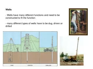
Wells - Wells have many different functions and need to be constructed to fit the function - many different types of wells have to be dug, driven or drilled
1. Extraction well - - provides water for domestic, industrial, or agricultural uses - can also be installed for dewatering (e.g. construction sites) - location of extraction wells with regards to property lines, septic systems, etc. are usually regulated - before drilling, need to study local geology, and nearby well logs - if no logs are available nearby, test borings may be necessary
-sedimentary formations your best bet - even in regions with poor aquifers it may be possible to intersect several layers of higher permeability - - fracture traces are surface expressions of fractures thinly covered with sediment (could be a zone of different coloured vegetation , shallow ditch or dip, or zone of wetter soil - fracture traces often linear and aligned with local structural features - fracture traces can sometimes be easier to detect on a air photograph than on the ground - don’t confuse with buried pipelines/utilities - ground truth
2. Recovery wells - recovers contaminants or contaminated water from the groundwater (e.g. gasoline that has leaked from an underground storage container) - many of the considerations fro extraction wells apply here, except that: a. instead of going for the biggest water yield, the target is the specific formation that holds the contaminant. - this may be a low K aquifer requiring larger well diamter and/or longer well intakes b. - fluid properties may be very different from water - need to consider not only hydrogeology but also contaminant source, chemcial and physical properties, and transport mechanisms - can make for complex designs
3. Monitoring wells - for obtaining chemically representative water samples - in some situations can yield useful water level data as “well” - often want to know character of water flowing into, and out of a site, so: a. - placed in locations that allow them to intercept water flowing into a site - obviously need to determine direction of flow in formation first (local water table maps, piezometers, flow net, computer models such as modflow). - sometimes impossible to site an upgradient well (e.g. if site overlies a recharge zone - in these cases need to settle for a “background” well
b) - sample water leaving site - number of downgradient wells may be regulated depending on complexity of hydrogeology - may intercept contaminant plume, or be installed prior to construction at a site to monitor ground water quality - as with upgradient wells, flow directions must be determined to a high degree of certainty - however contaminants may not flow like water and the physcial and chemical properties of the contaminant need to be considered
4. - Well with short intake installed for the purpose of measuring hydraulic head, pressure head - location depends on data needed and purpose
5. - installed to provide conduit for the injection of water into a formation - - pump-and-treat systems pump contaminated water from aquifer, treat and reinject - purpose is to use aquifer to assist in remediation - reduces cost of transporting, treating, and disposing large volumes off-site - oilfield brine injection - oil pumping generates brine waste fluid - inject brine waste into deep aquifers that hold nonpotable water - injection is also used to intentionally change hydraulic gradient - change direction of contaminant plume by injecting water in its path - some experimentation in injection of water to lubricate faults to relieve stress - well networks can be constructed to provide water supply more effectively, deliniate contaminant plumes, capture contaminants, or determine flow conditions throughout an area
Flow to wells - pumping from wells has two implications: 1. if the aquifer properties are known, we can calculate the amount and extent of drawdown (and aquifer compaction) associated with the pumping 2. If the aquifer properties are not known, we can determine them in situ by pumping and making observations at surrounding well locations Start with 1. - - pumping causes drawdown in a cone around the well - cone of depression or pumping cone See assumptions of all following calculations in Fetter section 5.2
The following several pages describes how to calculate drawdown from pumping from: 1. 2. A confined aquifer where leakage occurs, but no release of water from the confining layer from compaction 3. A confined aquifer where leakage occurs, with addition realease fo water from compaction 4. an unconfined aquifer
1. Flow in a completely Confined Aquifer Theis Equation can replace integral in Theis equation with infinite series: where Q is constant pumping rate h is head at some point r after pumping h0 is head before pumping h0-h is the drawdown T is transmissivity (e.g. m2/day) t is time since pumping began (e.g. days) r is radial dist from well (e.g. m) S is storativity (dimensionless)
where b is the saturated thickness of the aquifer and Ss is the specific storage, amount of water per unit volume that is stored or expelled from storage due to compressibility of the aquifer and water per unit change in head The infinate series in the above equation is termed the well function and is sometimes just noted as W(u). It can easily be evaluated on a spreadsheet, but there are also tables available of W(u) for a given u
2. case where no water drains from confining layer (see fetter ch 5 for myriad of assumptions) • All water flowing to well is either from the aquifer or flows across the confining layer from a source bed above (unconfined aquifer) • two key assumptions: • a) The water table in the source bed does not fall during pumping • the assumption is valid if either of the following is true: • or • where t is the time since pumping began • S’ is the aquitard storativity • S is the storativity of the confined aquifer • b’ is the thickness of the aquitard • b is the thickness of the confined aquifer • b” is the thickness of the water table aquifer • K’ is the vertical hydraulic conductivity of the aquitard • K” is the hydraulic conductivity of the water table aquifer • K is the hydraulic conductivity of the confined auifer
b) no water from elastic storage (compaction) of confining layer test this by where S’ is the storativity of the aquitard b’ is the thickness of the aquitard K’ is the hydraulic conductivity of the aquitard if this is true can use (if not true see next section): Hantush-Jacob formula where Q is pumping rate h0-h is the drawdown in the confined aquifer W(u, r/B) is the leaky artesian well function (gotten from tables) r is distance from pumping well to obs well t is time since pumping began B is a leakage factor b’ is the thickness of the confining layer K’ is the hydraulic conductivity of the aquitard
when all water will be coming from leakage across the confining layer and the drawdown can be found by: where Ko is a function found in tables
3. Case where some water comes from elastic storage in confining layer – see Fetter 4. pumping from unconfined aquifers - – see Fetter
Aquifer testing using wells 1. - way of measuring in situ values for K - only gives value of K immediately around well - instantaneous change in water level caused in a well, and rate t which the head returns to original level is measured - faster rebound, higher K
- “slug” may be: a) b) a bailer (open slug filled with clean water on entry) - can act as a solid slug if filled with water at the surface, or bail water to drop head c) a slug of clean water -problems with this are time it takes to pore water, only falling head test can be performed, alteration of water chemistry in the well d) pneumatic slug - use enforced pressure change to change head -no introduction of foreign materials
- two types of slug test: • a) • - instantaneous rise in level and record to return • - raise head with slug instantaneously and record highest level and record drop over time • - depending on material recovery could take days to months • in high K material, use of a transducer and datalogger will be essential • b) • - instantaneous drop in level and record return • - often conducted right after a falling-head test • - same principals
- h0 is the difference between the pretest level and level after initial rise or fall caused by slug h is the difference after some time t - find t0 which is “basic time lag” = time for h/h0 to reach 0.37 calculate K by (Hvorslev method): where: r is radius of well or piezometer casing R is the radius of the screen Le is the length of the well screen T37 = time for water to rise or fall 37% of intitial change
2. - used for in situ assessment of transmissivity and storativity and K - water pumped out at known rate over hours or days - water levels monitored in nearby observation wells, and in pumping well - wells are pumped preferably until the water levels reach a state of equilibrium - i.e. no further drawdown over time - during pumping, cone of depression grows until it reaches a recharge boundary. At this point we have steady state
Steady Flow Tests (i.e. pumping for a long time) - generally more accurate in determination - more limited in scope of aquifer properties acquired because no drawdown occurring over time For a situation where you have: 1. Steady flow (e.g. long pumping rates) 2. A pumping well screened through the entire sat. thickness 3. two obs wells at distances r1 and r2 4. totally confined
which can be rearranged into the Theim equation for an confined aquifer: can not be used to determine storativity since there is no change in head over time at steady state so nothing coming from storage Theim equation for an unconfined aquifer is: all as above but now a water table aquifer
Nonequilibrium Tests - pump well at a constant rate for a period of time - measure drawdown in one or a number of obs wells - get drawdown over time -Plot data (do not connect points) and compare to plot at same on same log paper of W(u) vs 1/u (Theis type curve) - on type curve paper select a match point doesn’t have to be on the line (often W(u)=1, 1/u = 1) - find h0-h and t corresponding to match point take obtained values at match point and put in below equations:
Theis equation can be re-written as: Equation for u in Theis approach can also be re-written as: These equations are only valid at the match point Doing this at several obs wells can tell about homogeneity
Jacob-Straight-line Method If u<0.05, higher powers of u in inifinate series can be ignored and the Theis equation can be rewritten as: or rewritten as a base 10 equation: this equation should plot on a straight line if u is truely small (occurs when t gets big or r is small).
1. Plot drawdown vs time on semilog paper • 2. Draw straight line through data and extent it to the zero drawdown line. This time at this value (x-intercept) will be positive and be denoted t0. • 3. calculate the drawdown per log cycle, Δ(ho-h), which is the slope of the line • and
Leaky Aquifers - type curve methods have been developed for different leaky aquifer situations - approached same way as in the Theis graphical method described above, just using different sets of curves - Fetter Ch 5 has excellent discussion of different techniques, and examples - essentially what you do is plot drawdown vs time for your aquifer in the same way, and find the appropriate curve that fits from a series a type curves for different leakage conditions - type curves can be made for W(u, r/B) vs 1/u where lines are plotted for various r/B values (for no storage) -
Intersecting pumping cones - often several pumps are used in the same aquifer - e.g. many property owners tapping the same regional aquifer - results in intersecting pumping cones - - for unconfined aquifers, if drawdown is significant compared to saturated thickness, calculated linear composite drawdown will under-estimate actual drawdown - Interference needs to be considered in locating wells. Will affect well design (e.g. horsepower required for pump).
Pumping and Boundaries • - pumping cones extend until they reach a point where vertical recharge supplies the flow, or a hydrogeologic boundary is reached • - boundaries are either recharge or barrier boundaries • - region where aquifer is replenished • Barrier boundary - termination point of aquifer by thinning, hitting a low-permeability formation, or erosion • - effect of a recharge boundary is to the rate of drawdown • effect of a barrier boundary is to the drawdown rate • for confined aquifers pumping cone behavior can be predicted using method of images
- real bounded system is replaced by imaginary system of infinite areal extent and
Similar approach can be used for a confined aquifer in the vicintity of a contant head boundary - in this case there is a discharging real well, and recharging image well