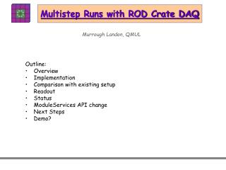
TIM tests with ROD Crate
150 likes | 178 Vues
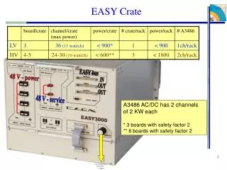
TIM tests with ROD Crate. John Hill. Test Setup. Readout facility at Cambridge with: Three detector modules on single pre-series SCT barrel harness Power from SCT prototype LV and HV cards

TIM tests with ROD Crate
E N D
Presentation Transcript
TIM tests with ROD Crate John Hill ATLAS Pixel/SCT TIM FDR/PRR
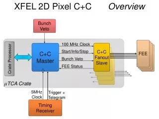
Test Setup • Readout facility at Cambridge with: • Three detector modules on single pre-series SCT barrel harness • Power from SCT prototype LV and HV cards • Series ROD (Rev E) and BOC (Rev C) (transition card housing all incoming and outgoing fibre connections) with opto-plugins connected to harness fibre ribbons. • TIM-3A • CCT VP110 as SBC (current ATLAS standard CPU) • DAQ is SCTRODDAQ, developed for Macro-Assembly, but using ATLAS T/DAQ components where possible – and so hopefully the basis of the SCT ROD Crate DAQ. • Purpose of tests are to confirm that TIM interface to ROD and BOC is working correctly. ATLAS Pixel/SCT TIM FDR/PRR
LV/HV 6U VME crate 6-way fibre ribbon (Clock and Control) Conventional Electrical Cables 9U VME64x crate Patch Panel 12-way fibre ribbon (Data) Module 1 Module 2 Module 3 Low-mass Electrical tapes Schematic of layout for tests ATLAS Pixel/SCT TIM FDR/PRR
Simple tests • The following basic signals need checking: • TTC signals from TIM to RODs. Eight signals (L1A,ECReset, BCReset, CAL, Serial ID, Serial TT, FEReset, Spare) are supplied to each ROD. • ROD BUSY from each ROD to TIM. • 40MHz clock supplied to RODs from TIM. Clock is in fact supplied from TIM to BOC and then redistributed to the ROD. ATLAS Pixel/SCT TIM FDR/PRR
TTC signals • Do the TTC signals propagate from TIM to ROD correctly? • L1A (TTC0) must be seen for triggering to occur at all. • ECR (TTC1) is counted in the top nibble of the L1ID, and synchronises the L1ID in the ROD and Front Ends. • BCR (TTC2) is required to synchronise the BC number in the ROD and Front Ends. • Serial ID (TTC4) – the ROD will not generate events until this is received, and the data must match that expected. • Serial TT (TTC5) – events should contain the Trigger Type as generated in the TIM. • FER (TTC6) and spare (TTC7) are not used by ROD – all we can do is look for signals on a scope. • CAL(TTC3) is not used in subsequent test – only employed when want to generate a calibrate pulse for the front ends. ATLAS Pixel/SCT TIM FDR/PRR
TTC signals • Background to this test: • Setup ROD to accept triggers from TIM (rather than generated internally). • Setup ROD and BOC in data-taking mode. • Setup TIM to generate triggers with correct BC offset (to allow for propagation time of commands to front ends). • Generate a BCR to synchronise Bunch Count in ROD and front ends. • Generate a ECR to synchronise Event Count. This also has effect of incrementing the ECR counter in the ROD (see the L1IDs reported in the following events). • Generate eight TIM triggers with Trigger Type changing for each event. • Use “root” interface to SCTRODDAQ (full GUI for TIM triggers is not yet ready for use). ATLAS Pixel/SCT TIM FDR/PRR
Decode first event Correct trigger type Loop setting Trigger Type to 1,2,4,… and then generating a single TIM trigger Data due to module in “send mask” mode Last event L1ID=0x1000007 ECR Count = 1 First event L1ID=0x1000000 ATLAS Pixel/SCT TIM FDR/PRR
No BCID or L1ID errors Decode last event Correct trigger type (=27) ATLAS Pixel/SCT TIM FDR/PRR
again no BCID or L1ID errors (The other events were checked and were as expected) These events indicate that TTC0-2, TTC4-TTC5 are transmitted correctly and with the appropriate synchronisation. ATLAS Pixel/SCT TIM FDR/PRR
ROD BUSY • Three registers on TIM related to ROD BUSY: • ROD BUSY – bit only set when BUSY present. • ROD Latch – latches bit if BUSY present since cleared. • ROD Monitor – latches bit if BUSY present for some time. • Test by resetting the ROD – this creates a busy signal for several seconds (there is no way to get the ROD to generate a BUSY by e.g. setting a register). Monitor the above registers at 100msec intervals. • Find that behave as expected – ROD BUSY only on when ROD BUSY set, other two registers latch. • All 16 ROD slots tested – correct bit set on each occasion (and the correct front panel LED on the TIM comes on). Necessary because the ROD BUSY line from each slot is on a separate backplane line. • ROD BUSY appears to be handled correctly by the TIM. ATLAS Pixel/SCT TIM FDR/PRR
Clocks • Sample the clock as supplied by TIM on the BOC. • Use a full (16 RODs+BOCs) crate for this test - hopefully the worst case scenario. • Check the clock when the system is not running (apart from general transmission of clocks around the various components!) and when data is being read from the 3 modules using triggers from the TIM, in the same way as for the TTC test. • Look for jitter on the clock as seen by the BOC a significant distance (1μs) downstream of the scope trigger point. • ROD+BOC doing the readout are in slot 21 to maximise distance from TIM (again worst-case?). ATLAS Pixel/SCT TIM FDR/PRR
Clocks Jitter on clock on BOC in slot 21, no data taking Jitter on clock on BOC in slot 21, data taking with TIM triggers at 6kHz Sigma of distributions very similar – hint that jitter is slightly more with triggers running. ATLAS Pixel/SCT TIM FDR/PRR
Clocks Jitter on clock on BOC in slot 20, no data taking Jitter on clock on BOC in slot 20, data taking in slot 21with TIM triggers at 6kHz Again a slight hint that the right-hand plot is wider ATLAS Pixel/SCT TIM FDR/PRR
Other tests • A number of other tests have been done using triggers from the TIM, but need further work before being presentable: • Calibration scans – a couple of these have been tried, but bugs remain in the ROD and DAQ software – changes are very new here and rely on a single expert in each case. • Data taking via S-link has been demonstrated using TIM triggers (and internally-generated triggers!), but there are known VHDL bugs which corrupt the data when XOFF occurs. S-link is not needed for Macro Assembly, so this has been a lower-priority item. ATLAS Pixel/SCT TIM FDR/PRR
Summary • Tests indicate that TIM interface to/from ROD and BOC is working as expected. • Some hint that triggers from the TIM might be increasing the clock jitter – more tests are required here to check this out. • More sophisticated tests (calibration scans) are needed – these are required for Macro Assembly in any case for crosstalk studies and so will be developed in the near future. ATLAS Pixel/SCT TIM FDR/PRR