Download
1 / 32
320 likes | 538 Vues
Lecture 15 Coding in Verilog. EEE4084F. Digital Systems. module myveriloglecture ( techniques_out , wishes_in ); … // implementation of today’s lecture … endmodule. Lecturer: Simon Winberg. Basics of Verilog coding Exercise Verilog simulators. Lecture Overview.

E N D
Lecture 15 Coding in Verilog EEE4084F Digital Systems module myveriloglecture ( techniques_out, wishes_in ); … // implementation of today’s lecture … endmodule Lecturer: Simon Winberg
Basics of Verilog coding Exercise Verilog simulators Lecture Overview
Tends to be more popular in industry than VHDL VHDL is used quite widely in Europe (so is Verilog). Verilog used mostly in USA. Easier to learn since it is similar to C Why consider Verilog?
History of Verilog • 1980 Verilog developed by Gateway Design Automation (but kept as their own ‘secret weapon’) • 1990 Verilog was made public • 1995 adopted as IEEE standard 1364-1995 • 2001 enhanced version: Verilog 2001 Lead in to Verilog…
Module: the basic block that does something and can be connected to (i.e. equivalent to entity in VHDL) Modules are hierarchical. They can be individual elements (e.g. comprise standard gates) or can be a composition of other modules. Module: Building block of Verilog Programs module <module name> (<module terminal list>); … <module implementation> … endmodule SYNTAX: … module2 module1
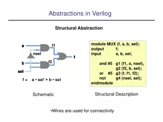
Switch Level Abstraction (lowest level) • Implementing using only switches and interconnects. • Gate Level (slightly higher level) • Implementing terms of gates like (i.e., AND, NOT, OR etc) and using interconnects between gates. • Dataflow Level • Implementing in terms of dataflow between registers • Behavioral Level (highest level) • Implementing module in terms of algorithms, not worrying about hardware issues. Close to C programming. Module Abstraction Levels Arguably the best thing about Verilog!!
Number format: <size>’<base><number> • Some examples: • 3’b111 – a three bit number (i.e. 710) • 8’ha1 – a hexadecimal (i.e. A116 = 16110) • 24’d165 – a decimal number (i.e. 16510) Syntactic issues:Constant Values in Verilog Defaults: 100 – 32-bit decimal by default if you don’t have a ‘ ‘hab – 32-bit hexadecimal unsigned value ‘o77 – 32-bit hexadecimal unsigned value (778 = 6310)
Wires (or nets) are used to connect elements (e.g. ports of modules) Wires have values continuously driven onto them by outputs they connect to Wires // Defining the wires // for this circuit: a c d wire a; wire a, b, c; b
Registers store data Registers retain their data until another value is put into them (i.e. works like a FF or latch) A register needs no driver Registers reg myregister; // declare a new register (defaults to 1 bit) myregister = 1'b1; // set the value to 1
// Define some wires: wire a; // a bit wire wire [7:0] abus; // an 8-bit bus wire [15:0] bus1, bus2; // two 16-bit busses // Define some registers reg active; // a single bit register reg [0:17] count; // a vector of 18 bits Vectors of wires and registers
Integer 32-bit value integer i; // e.g. used as a counter • Real 32-bit floating point value real r; // e.g. floating point value for calculation • Time 64-bit value time t; // e.g. used in simulation for delays Data types
Parameter: a the rather obscurely named ‘parameter’ works more like a constant in C (or generic in VHLD) Initial: used to initialize parameters or registers or describe a process for initializing a module (i.e. like constructor in C++) Use both in implementation of a module Verilog Parameters & Initial block Example use:
The tradition is to list output ports first and then input ports. This makes reading of code easier. i.e.: ModuleName ( <output ports> <input ports>); Ports module mygate ( xout, // 1 bit output clk , // clock input ain ); // a 1 bit input // define outputs output xout; // define inputs input clk, ain; … rest of implementation … endmodule mygate clk xout ain
These are output port that hold their value. An essential feature needed to construct things like timers and flip flops Register Output Ports module mycounter ( count_out, // 8 bit vector output of the clk ); // Clock input of the design // Outputs: output [7:0] count_out; // 8-bit counter output // All the outputs are registers reg [7:0] count_out; // Inputs: input clk; … endmodule
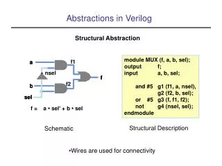
These two tasks usually done in one go… Modules are instantiated within modules Instantiating modules and connecting up ports • Syntax: <module name> <instance name> (<arguments>) // Multiplexer implemented using gates only* module mux2to1 (a,b,sel,y); input a,b,sel; output y; wire sel,asel,bsel,invsel; not U_inv (invsel,sel); and U_anda (asel,a,invsel), U_andb (bsel,b,sel); or U_or (y,asel,bsel); endmodule EXAMPLE: U_inv invsel sel U_anda asel U_or a y Module instance names bsel b U_andb Port mapping (like arguments in a C function call) * Based on source: http://www.asic-world.com/code/hdl_models/mux_2to1_gates.v
Why give instances names? • In Verilog 2001 you can do: module mux2to1 (input a, input b, input sel, output y); … and (asel,a,invsel), // can have unnamed instance … endmodule Instantiating modules Major reason for putting a name in is when it comes to debugging: Xilinx tends to assign instance names arbitrarily, like the and above might be called XXYY01 and then you might get a error message saying something like cannot connect signals to XXYY01 and then you spend ages trying to track down which gate is giving the problem.
Verilog Primitive Gates Examples: and or not and a1 (OUT,IN1,IN2); nand nor xor not n1 (OUT,IN); Buffer (i.e. 1-bit FIFO or splitter) buf Example: bufonelinkbuf (OUT, IN); buftwolinkbuf (OUT1, OUT2, IN);
BufIf (hardware if gate) Tri-state buffer. Can choose to drive out with value of in (if ctr = 1) or don’t drive anything to out (i.e. if ctr = 0 connect high impedance to out) in out bufif1 operation ctr in ctr bufif1 (out, in, ctr) See also notif (works in the apposite way: if ctr=0 then drive out with in)
The preceding slides have given a very brief look at Verilog, but has covered much of the major things that are used most commonly. It’s best to get stuck into experimenting and testing code in order to learn this language Where to go from here… Some thoughts for experimenting to do…
Learning Verilog By Example EEE4084F
Take-home assignment A B Sum Carry C This is a 4-bit adder design. Try to convert this into Verilog. Try to run on one or a few of the simulation tools presented in next slides…
Learning Verilog using Simulators If you’ve got your own laptop / PC consider installing one of the simulators* as a quick way to check syntax and test designs. Various simulators installed on forge.ee, can be accessed remotely * I confess to using Altera Quartus II much of the time since it takes less space to install and runs faster than its obvious rival.
Learning Verilog One approach is using a block diagram and converting to Verilog HDL. E.g. using Alterna Quartus II (See test1.zip for example Quartus project)
Learning Verilog One approach is using a block diagram and converting to Verilog HDL. E.g. using Alterna Quartus II See how param types are specified See how included modules are instantiated and ports mapped
Checking syntax I find a handy tool is the file analyser tool in Quartus II. This can be used to check the syntax of the file without having to go through the whole build process.
(See test2.zip for example Quartus project that contains only Verilog files and waveform file) Testing Running the simulation should allow you to verify the design is working as planned (i.e. NANDing) Load the Test2 file, if using Quartus make sure that mynand is the top level Entity
Consistent indentation • Align code vertically on the = operator • Use meaningful variable names • Include comments (i.e. C-style // or /**/ ) • brief descriptions, reference to documents • Can also be used to assist in separating parts of the code (e.g. indicate row of /*****/ to separate different module implementations) Verilog Recommended Coding Styles Source: Coram: Verilog-A Introduction for Compact Modelers (MOS-AK Montreux 2006)
See Verilog tutorials online, e.g.: • http://www.verilogtutorial.info/ • Icarus Verilog – An open-source Verilog compiler and simulator • http://iverilog.icarus.com/ • Try iverilog on forge.ee • Gplcver – Open-source Verilog interpreter • http://sourceforge.net/projects/gplcver/ • Try cver on forge.ee • Verilator – An open-source Verilog optimizer and simulator • http://www.veripool.org/wiki/verilator Suggested study ideas… Comprehensive list of simulators: http://www.asic-world.com/verilog/tools.html
Icarus Verilog Probably the easiest free open-source tool available Excellent for doing quick tests. Takes very little space (a few megs) & runs pretty fast. Installed on forge.ee For Ubuntu or Debian you can install it (if you’re linked to the leg server), using: apt-get install iverilog Iverilog parsing the Verilog code and generates an executable the PC can run (called a.out if you don’t use the flags to change the output executable file name) I suggest the following to get to know iverilog… upload mynand.v example to forge.ee, compile it with iverilog. Run it. Try changing the testbest code, put in some more operations • http://iverilog.icarus.com/
More Experimenting Try test3 or mycounter.v as a more involved program and test Experiment with using both Altera Qauartus II, Icarus Verilog, and Xilinx ISE ISim
Remember to try doing the 4-bit adder example (see slide 21) • Next lecture: • RC Architectures Conclusion & Plans for Next lecture