Download
1 / 17
170 likes | 340 Vues
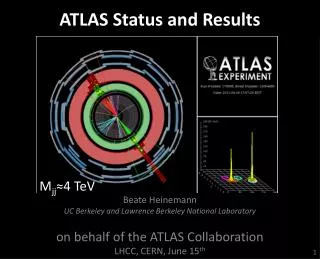
International Europhysics Conference on High Energy Physics EPS 2003, July 17th-23rd 2003 , Aachen, Germany. Performance of ATLAS & CMS Silicon Tracker. Alessia Tricomi University and INFN Catania. p-p collision @ √s = 14 TeV bunch spacing of 25 ns Luminosity

E N D
International Europhysics Conference on High Energy Physics EPS 2003, July 17th-23rd 2003, Aachen, Germany Performance of ATLAS & CMS Silicon Tracker Alessia Tricomi University and INFN Catania
p-p collision @ √s = 14 TeV bunch spacing of 25 ns Luminosity low-luminosity: 2*1033cm-2s-1 (first years) high-luminosity: 1034cm-2s-1 ~20 minimum bias events per bunch crossing ~1000 charged tracks per event Radius: 2cm 10cm 25cm 60cm NTracks/(cm2*25ns) 10.0 1.0 0.10 0.01 Severe radiation damage to detectors H bb event H bb event @ high luminosity What LHC means… Plus 22 minimum bias events Challenging requirements for the Tracking system EPS 2003 17-23 July, Aachen
Tracker Requirements • Efficient & robust Pattern Recognition algorithm • Fine granularity to resolve nearby tracks • Fast response time to resolve bunch crossings • Ability to reconstruct narrow heavy object • 1~2% pt resolution at ~ 100 GeV • Ability to operate in a crowded environment • Nch/(cm2*25ns) = 1.0 at 10 cm from PV • Ability to tag b/t through secondary vertex • Good impact parameter resolution • Reconstruction efficiency • 95% for hadronic isolated high pt tracks • 90% for high pt tracks inside jets • Ability to operate in a very high radiation environment • Silicon detectors will operate at -7°C -10°C to contain reverse annealing and limit leakage current EPS 2003 17-23 July, Aachen
~ 4 Tesla Toroid Field 2.3 m x 5.3 m Solenoid ~ 2 Tesla Field ATLAS 46m Long, 22m Diameter, 7’000 Ton Detector Two different strategies… • ATLAS Inner Detector • ID inside 2T solenoid field • Tracking based on many points • Precision Tracking: • Pixel detector (2-3 points) • Semiconductor Tracker – • SCT (4 points) • Continuous Tracking: • (for pattern recognition & e id) • Transition Radiation Tracker – • TRT(36 points) EPS 2003 17-23 July, Aachen
13m x 6m Solenoid: 4 Tesla Field Tracking up to h~ 2.4 Muon system in return yoke Pixel End cap –TEC- Outer Barrel –TOB- First muon chamber just after solenoid Extended lever arm for pt measurement Inner Barrel –TIB- CMS Inner Disks –TID- 2.4 m ECAL& HCAL Inside solenoid 5.4 m volume 24.4 m3 running temperature – 10 0C dry atmosphere for YEARS! Two different strategies… CMS has chosen an all-silicon configuration • CMS Tracker • Inside 4T solenoid field • Tracking rely on “few” measurement layers, each able • to provide robust (clean) and precise coordinate determination • Precision Tracking: • Pixel detector (2-3 points) • Silicon Strip Tracker (220 m2) – SST (10 – 14 points) 22m Long, 15m Diameter, 14’000 Ton Detector EPS 2003 17-23 July, Aachen
3 barrel layers* r = 5.05 cm (B-layer), 9.85 cm, 12.25 cm 3 pairs of Forward/Backward disks r= 49.5 cm, 6.0 cm, 65.0 cm ~ 2% of tracks with less than 3 hits Fully insertable detector Pixel size: 50 mm x 300 mm (B layer) & 50 mm x 400 mm ~ 2.0 m2 of sensitive area with 8 x 10⁷ ch Modules are the basic building elements 1456in the barrel +288in the endcaps Active area16.4 mm x 60.8 mm Sensitive area read out by 16 FE chips each serving a 18 columns x 160 row pixel matrix * Several changes from TDR The ATLAS Pixel Detector EPS 2003 17-23 July, Aachen
1.53 m 1.04 m 5.6 m The ATLAS SCT Detector • Endcap: 9 wheel pairs • pitch70 - 80 mm • 3 types of modules • Inner (400) • Middle (640 incl. 80 shorter) • Outer (936) • Barrel: 4 layers • pitch~ 80 mm • radii:284 – 335 – 427 – 498 mm • 2112modules, with 2 detectors per side, • read out in the middle • All detectors are double-sided • (40 mrad stereo angle) • 4088 modules • 61 m2 of silicon • 6.3 x 10⁶ channels EPS 2003 17-23 July, Aachen
3 barrel layers r = 4.1 – 4.6 cm, 7.0 – 7.6 cm, 9.9 – 10.4 cm ~ 32 x 106 pixels 2 pairs of Forward/Backward disks Radial coverage 6 < r < 15 cm Average z position: 34.5 cm, 46.5 cm Later update to 3 pairs possible (<z> ~ 58.2 cm) Per Disk: ~3 x 106 pixels 3 high resolution space points for h < 2.2 Pixel size: 150 mm x 150 mm driven by FE chip Hit resolution: r-f s ~ 10 mm (Lorentz angle 28° in 4 T field) r-z s ~ 17 mm Modules are the basic building elements 800in the barrel +315in the endcaps Occupancy is ~ 10-4 Pixel seeding fastest starting point for track reconstruction despite the extremely high track density The CMS Pixel Detector EPS 2003 17-23 July, Aachen
12 layers with (pitch/12) spatial resolution and 110 cm radius give a momentum resolution of Radius ~ 110cm, Length ~ 270cm h~1.7 6 layers TOB A typical pitch of order 100mm is required in the f coordinate To achieve the required resolution h~2.4 4 layers TIB FE hybrid with FE ASICS Pitch adapter 3 disks TID 9 disks TEC The CMS Silicon Strip Tracker 9’648’128 strips channels 75’376 APV chips 6’136 Thin sensors 18’192 Thick sensors 440 m2 of silicon wafers 210 m2 of silicon sensors 3’112 + 2*1’512 Thin modules 5’496 + 2*1’800 Thick modules ssds=b-to-b (100mrad) ~17’000 modules ~25’000’000 Bonds p+ strips on n-type bulk <100> crystal lattice orientation Polysilicon resistors to bias the strips Strip width over pitch w/p=0.25 Metal overhang and multiguard structure to enhance breakdown performance • Outer Barrel (TOB): 6 layers • Thick sensors (500 mm) • Long strips • Endcap (TEC): 9 Disk pairs • r < 60 cm thin sensors • r > 60 cm thick sensors Silicon sensors CF frame Strip length ranges from10 cmin the inner layers to 20 cmin the outer layers. Pitch ranges from 80mmin the inner layers to near200mmin the outer layers • Inner Disks (TIB): 3 Disk pairs • Thin sensors • Inner Barrel (TIB): 4 layers • Thin sensors (320 mm) • Short strips Black: total number of hits Green: double-sided hits Red: ds hits - thin detectors Blue: ds hits - thick detectors EPS 2003 17-23 July, Aachen
99% 99% Single m Dijet events <10-5 ET = 200 GeV Fake Rate < 8 *10-3 ET = 50 GeV Fake Rate < 10-3 Track reconstruction efficiency Efficiency for p is lower compared to m due to secondary interactions in the Tracker Efficiency can be increased by relaxing track selection CMS Global efficiency: selected Rec.Tracks / all Sim.Tracks Algorithmic efficiency: selected Rec.Tracks / selected Sim.Tracks (Sim.Track selection: at least 8 hits, at least 2 in pixel) Global efficiency limited by pixel geometrical acceptance Efficiency for particles in a 0.4cone around jet axis No significant degradation compared to single pions Loss of efficiency is dominated by hadronic interactions in Tracker material EPS 2003 17-23 July, Aachen
CMS CMS CMS CMS Track resolutions ATLAS & CMS have similar performance Good track parameter resolution already with 4 or more hits s(d0) mm s(pT)/pT For lower pt tracks multiple scattering becomes significant and the h dependence reflects the amount of material traversed by tracks EPS 2003 17-23 July, Aachen
ATLAS and CMS have thick trackers: each pixel layer contributes >2% X0 plus global support and cooling structures and thermal/EMI screens The momentum & impact parameter resolution depends strongly on: radius of innermost pixel layer thickness of pixel layers radius and thickness of beam pipe Example: effect of the new ATLAS layout: now (TDR) ATLAS & CMS performances s(d0) mm s(1/pT) TeV-1 EPS 2003 17-23 July, Aachen
2 1.5 1 0.5 0 ATLAS X/X0 -4 -2 0 2 4 h CMS CMS Reduces (somewhat) efficiency for usefully reconstructing H gg The dark side: material budget in the Tracker Degrades tracking performance, due to multiple scattering, Bremsstrahlung and nuclear interactions (see pt resolution and reconstruction efficiency) Dominates energy resolution for electrons EPS 2003 17-23 July, Aachen
CMS H 4 m ATLAS Primary vertex in A tt ATLAS & CMS Silicon Tracker: vertexing At LHC design luminosity ~ 20 interaction per beam crossing spread out by s(z)=5.6 cm Identification of primary and secondary vertices fundamental Pixel detectors allow fast vertex reconstruction with s(z)<50mm Slower but better resolution (15 mm) achievable using the full Tracker s ~ 40mm “easy” channel “difficult” channel s ~ 16mm uu 100 GeV h<1.4 Pixel Full Tracker Several algorithms available EPS 2003 17-23 July, Aachen
ATLAS & CMS Silicon Tracker: vertexing Secondary Vertex: Exclusive Vertices The basic tool for the vertexing classes is a general purpose fitter. Test onB0sJ/ f, withJ/ mm andf KK Secondary Vertex: Inclusive Vertices • Useful for b and t tagging • Two methods available and tested (Combinatorial method, d0/F method) The typical resolution using RecTracks is ~55 mm in the transverse plane and ~75 mm in z Typical efficiency ranges from~35%to ~25% for Track Purity>50% Difference between the simulated Bs decay vertex and the fitted one in transverse and longitudinal directions EPS 2003 17-23 July, Aachen
ATLAS & CMS Silicon Tracker: btagging • Typical performance for both experiments: • average: e(u) ~ 1% for e(b) = 60% for “interesting” jet pT range (50 < pT < 130 GeV) and all h • best: e(u) ~ 0.2% for e(b) = 50% for pT ~ 100 GeV and central rapidity • Several algorithms tried by CMS and ATLAS, based on: • impact parameter (track counting and jet probability • secondary vertex reconstruction • decay length CMS: 2-D & 3-D I.P. prob.:e(b) vs e(u) ATLAS: 2-D I.P. prob.: e(u) vs pT (all h) EPS 2003 17-23 July, Aachen
Conclusions • Tracking at LHC is a very challenging task: • Very high rates • Very harsh radiation environment • High accuracy needed • Extensive R&D programs carried on to design detectors which fulfil these requirements • Design of ATLAS & CMS Trackers almost complete • Production and construction of various components/detectors already started • Both ATLAS & CMS have robust performances: • Pixel detectors allow for fast and efficient track seed generation as well as vertex reconstruction • pt resolution of ~ 1% for 100 GeV muons over about 1.7 units of rapidity • Robust & efficient track reconstruction algorithms available (see D.Rousseau Talk) • Jet flavour tagging under study to improve and extend the Physics reach • Extensive use of track information @ HLT (see G. Bagliesi’s Talk) EPS 2003 17-23 July, Aachen